High current on neutral with a balanced load

Status
Not open for further replies.

jhardy13

Member
Location
Joplin Missouri
Occupation
Industrial Engineering student
120 watts on the neutral when no power is applied what so ever, can you pull the meter to see if that 1 amp goes away, maybe there is leakage somewhere on the line side of the meter ... either way I'd have a lot of fun trying all the tricks of troubleshooting I learned from the past, you certainly need to tell us what the culprit is when discovered.
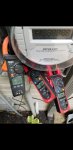
I will happily share what the cause of this is once I've tracked it down. As for pulling the meter, we tried that and we were still seeing small current on the neutral. It was fluctuating between 0.3-3.0 amps with the meter pulled. Whatever the cause is, its most likely on POCO's side of things. I fully intend to get to the bottom of this. Hopefully early next week I'll have some answers.
 

oldsparky52

Senior Member
Well, if turning off the main at the neighbor's house does not get rid of the neutral current I have one other wild thought.

If the water has enough minerals in it the water can be a very good conductor. The water (underground) probably makes a great connection to earth (unlike ground rods) and the water could be a parallel path back to the substation grounding. So, voltage drop or a degrading PoCo neutral connection could have some current coming from the PoCo neutral heading back to the substation via the water? Just reaching for straws, but my money is on the neighbor's neutral having problems.
 

synchro

Senior Member
Location
Chicago, IL
Occupation
EE
What are those wires coming into the meter base on the lower left? POCO load control or something else?
I don't know. I will be sure to ask the electrician next week. I am confident we can find the source through process of elimination.
I suggest putting the meter clamp around the entire group of wires coming in at the lower left, including the green wire. You shouldn't see any current because, as always, those wires are required to make complete circuits and so their magnetic fields should cancel out within the clamp.

Also if there's room to do so, try putting the clamp meter around the conduit bringing in those wires to make sure there's no current going through the conduit itself.
In either case if you see any current then compare it with the measured neutral current. You can try it with and without the main breaker turned on.
 

synchro

Senior Member
Location
Chicago, IL
Occupation
EE
If the clamp meter’s opening is large enough and there's clearance to do so, try putting a clamp around both “hot” service conductors L1 and L2. Then apply loads to get balanced currents on L1 and L2 as you’ve done before, but use 120V L-N resistive loads such as a space heater if you can (I realize it’s hot outside). L-L loads will not do much for this particular experiment. If L1 and L2 are 180 degrees out of phase and their currents are equal then the clamp around L1 and L2 should read no current. If it shows significant current then L1 and L2 must not be really 180 degrees apart, because if so the currents should cancel each other out at the meter.

You mentioned that the L1 and L2 voltages were 124.8V and 124.6V, which would sum to 249.4V. And in another post L1-L2 was 240V “on the dot.” Now perhaps the line voltage changed between the times these measurements were made, but if not it that would indicate that L1 and L2 are 148 degrees apart (using the law of cosines). If this were true then you could get a substantial current on the neutral with equal L1 and L2 currents. But finding phase angles in this manner when the voltages are close is very sensitive to the measurements and therefore prone to error.

Now it’s not likely that L1 and L2 are departing much from 180 degrees apart. But perhaps a load from the “high leg” terminal to the neutral terminal (208V) of a 4-wire 240V delta transformer arrangement could make that happen to some extent. Such loads are normally to be avoided. There may also be some other ways to get a departure from 180 degrees as well.
 

jhardy13

Member
Location
Joplin Missouri
Occupation
Industrial Engineering student
If the clamp meter’s opening is large enough and there's clearance to do so, try putting a clamp around both “hot” service conductors L1 and L2. Then apply loads to get balanced currents on L1 and L2 as you’ve done before, but use 120V L-N resistive loads such as a space heater if you can (I realize it’s hot outside). L-L loads will not do much for this particular experiment. If L1 and L2 are 180 degrees out of phase and their currents are equal then the clamp around L1 and L2 should read no current. If it shows significant current then L1 and L2 must not be really 180 degrees apart, because if so the currents should cancel each other out at the meter.

You mentioned that the L1 and L2 voltages were 124.8V and 124.6V, which would sum to 249.4V. And in another post L1-L2 was 240V “on the dot.” Now perhaps the line voltage changed between the times these measurements were made, but if not it that would indicate that L1 and L2 are 148 degrees apart (using the law of cosines). If this were true then you could get a substantial current on the neutral with equal L1 and L2 currents. But finding phase angles in this manner when the voltages are close is very sensitive to the measurements and therefore prone to error.

Now it’s not likely that L1 and L2 are departing much from 180 degrees apart. But perhaps a load from the “high leg” terminal to the neutral terminal (208V) of a 4-wire 240V delta transformer arrangement could make that happen to some extent. Such loads are normally to be avoided. There may also be some other ways to get a departure from 180 degrees as well.
This is very useful information. I will test all of this as soon as I can. I will check line to line voltage and see if it matches adding each phase seperately. If they don't match, what would be my best course of action?
 

synchro

Senior Member
Location
Chicago, IL
Occupation
EE
This is very useful information. I will test all of this as soon as I can. I will check line to line voltage and see if it matches adding each phase seperately. If they don't match, what would be my best course of action?
If the sum of L1-N and L2-N voltages does not match the line-to-line value, I would still try to do the current measurement above to see if it can explain your issues with the neutral current. I think the current measurement is more definitive than the voltage measurements because the voltage comparison can be error prone in this situation, as I mentioned above. But checking for mismatched voltages is worthwhile to help confirm what may be causing the observed neutral current.

If the voltages don't match well then it's likely an issue with power company assets, and so all you can do is contact them about it. If it's not a safety related issue they may be less responsive. Perhaps Hv&Lv could provide an input about this.
 

jhardy13

Member
Location
Joplin Missouri
Occupation
Industrial Engineering student
Okay I have an update. I had a good electrician out today and we eliminated a bunch of possible causes. The current is not coming from our neighbor and it is not coming from the well pump. We checked the wiring and amperage thoroughly. We tested our home's ground, the tranformer's ground, and our neighbor's ground. All are under 15ohms. Currently when we shut the house power off, the neutral current drops to zero. All of this points to the source of the problem being in our home. We then started shutting off breakers one at a time to see if any breakers had an affect. None of the breakers fixed the problem. Here is another picture of the neutral current. This is the worst I have seen it. What we know now is that the current is NOT coming into our home. It is leaving our home. Therefore it must be a phase angle issue or something else. Line to line voltage is slightly off. About 2 volts. We plan on having POCO out in the next couple of days to meg our buried lines as well as out neighbors. If that doesn't reveal anything, I am at a loss.
 

Attachments

  • Screenshot_20200713-175308_Gallery.jpg
    Screenshot_20200713-175308_Gallery.jpg
    1.4 MB · Views: 35

Hv&Lv

Senior Member
Location
-
Occupation
Engineer/Technician
Okay I have an update. I had a good electrician out today and we eliminated a bunch of possible causes. The current is not coming from our neighbor and it is not coming from the well pump. We checked the wiring and amperage thoroughly. We tested our home's ground, the tranformer's ground, and our neighbor's ground. All are under 15ohms. Currently when we shut the house power off, the neutral current drops to zero. All of this points to the source of the problem being in our home. We then started shutting off breakers one at a time to see if any breakers had an affect. None of the breakers fixed the problem. Here is another picture of the neutral current. This is the worst I have seen it. What we know now is that the current is NOT coming into our home. It is leaving our home. Therefore it must be a phase angle issue or something else. Line to line voltage is slightly off. About 2 volts. We plan on having POCO out in the next couple of days to meg our buried lines as well as out neighbors. If that doesn't reveal anything, I am at a loss.
The POCO is going to meg your lines and the neighbors?
I’m interested to see if they really do that...
 

LarryFine

Master Electrician Electric Contractor Richmond VA
Location
Henrico County, VA
Occupation
Electrical Contractor
Currently when we shut the house power off, the neutral current drops to zero.
Pun intended? :giggle:

All of this points to the source of the problem being in our home. We then started shutting off breakers one at a time to see if any breakers had an affect. None of the breakers fixed the problem.
You're saying with all branch breakers off, if you turn on only the main, the current appears? o_O

If not, then I would turn on only the main, and turn on, and than back off one circuit at a time.
 

jhardy13

Member
Location
Joplin Missouri
Occupation
Industrial Engineering student
Pun intended? :giggle:


You're saying with all branch breakers off, if you turn on only the main, the current appears? o_O

If not, then I would turn on only the main, and turn on, and than back off one circuit at a time.
No, turning each breaker off lowered the current on the neutral but the excess current was always present until the mains 200amp breaker was turned off.
 

kwired

Electron manager
Location
NE Nebraska
If current is coming in/going out on the grounded service conductor and the ungrounded conductors have been isolated from being able to supply any line to neutral loads then an equal amount has to be going out/coming in on either a branch neutral an EGC or the GEC or it could be split between any of those.

Keep in mind this current could even be from another source (like POCO's primary neutral) and just happened to find a convenient path to follow somehow. Remember current doesn't take path of least resistance it takes all possible paths. The one with least resistance will have the most current on it though.
 

synchro

Senior Member
Location
Chicago, IL
Occupation
EE
Can you get the clamp around the neutral conductor further away from the watt-hour meter, or measure the neutral inside the breaker panel instead? It's a long shot, but it's just to make sure that the clamp meter isn't picking up a stray magnetic field from the stator of the watt-hour meter.
 

jhardy13

Member
Location
Joplin Missouri
Occupation
Industrial Engineering student
Can you get the clamp around the neutral conductor further away from the watt-hour meter, or measure the neutral inside the breaker panel instead? It's a long shot, but it's just to make sure that the clamp meter isn't picking up a stray magnetic field from the stator of the watt-hour meter.
We tested this in our panel at the same time. Six clamps. The results are the same.
 

synchro

Senior Member
Location
Chicago, IL
Occupation
EE
Does your PicoScope have two input channels? If so, it would be helpful to compare the voltage waveforms of L1-N and L2-N to make sure they are close to 180° apart and not some other angle.
 

oldsparky52

Senior Member
Okay I have an update. I had a good electrician out today and we eliminated a bunch of possible causes. The current is not coming from our neighbor and it is not coming from the well pump. We checked the wiring and amperage thoroughly. We tested our home's ground, the tranformer's ground, and our neighbor's ground. All are under 15ohms. Currently when we shut the house power off, the neutral current drops to zero. All of this points to the source of the problem being in our home. We then started shutting off breakers one at a time to see if any breakers had an affect. None of the breakers fixed the problem. Here is another picture of the neutral current. This is the worst I have seen it. What we know now is that the current is NOT coming into our home. It is leaving our home. Therefore it must be a phase angle issue or something else. Line to line voltage is slightly off. About 2 volts. We plan on having POCO out in the next couple of days to meg our buried lines as well as out neighbors. If that doesn't reveal anything, I am at a loss.
I don't think it matters, but I'm curious as to why all 3 meters are not using the same setting?
 
Status
Not open for further replies.
Top