How to determine the SMA Inverter's exact Breaker KAIC value when installed on a combiner box.

Status
Not open for further replies.

inforaj

Member
Location
Chiago
Occupation
Member
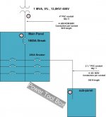
In most cases, we begin our calculations with the transformer, main breaker, and branch breaker.
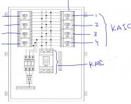
However, when doing a solar project, we may estimate from the main breaker and inverter breaker for the combiner box by taping to the utility line.
How do you determine the precise value of Breaker KAIC without a transformer when the Inverter has provided the total OCPD per specifications?

The general electrical calculation for Electrical Panel.
First, we will calculate the full load current for the 1MVA transformer.
I F.L = P  / (1.73 * V L-L ); where P is the transformer power rating in VA, and V L-L is the line to line RMS voltage at the secondary side of the transformer.
I F.L = 1,000,000/ 1.73*480 =  1,202 A; the I F.L is the full load current of the transformer. Now, to find the short circuit rating of point 1.
I S.C. for 3 Ph = I F.L /Z%; where I.S.C. is the short circuit current, and Z% is the transformer impedance; which usually can be obtained from the local utility company. I S.C. 3 ph for point 1 = 1202 /0.05 = 24,506 A or 24.5 KA (this is the available short circuit current at point 1)
F = (1.73 *50 *24,506) / (28,303*5*480) = 0.031206 ,
M = 1/(1+F) = 0.969738; where M is the multiplier, I S.C. 3 ph for point 2 = 24506* M = 24506*0.969738 = 23,764 A or 23.7 KA (this is the available short circuit current at point 2)
 

Attachments

  • KAIC CALCULATION.jpg
    KAIC CALCULATION.jpg
    47.8 KB · Views: 18
I'm not sure what you mean by calculating it without a transformer.
I am curious about the breaker KA or KAIC value for the Main Breaker and branch breaker for the Combiner Box. We may assume SMA CORE1 62.5KW Inverter has 79.5 Amp, 480V. But when these inverters are connected to the Combiner box, then how to know what size of the KAIC capacity of the breaker will be required?

1674252907189.png
 

Attachments

  • Combiner box breaker.JPG
    Combiner box breaker.JPG
    53.5 KB · Views: 13
I am curious about the breaker KA or KAIC value for the Main Breaker and branch breaker for the Combiner Box. We may assume SMA CORE1 62.5KW Inverter has 79.5 Amp, 480V. But when these inverters are connected to the Combiner box, then how to know what size of the KAIC capacity of the breaker will be required?

View attachment 2563671
The kAIC rating of the breaker has nothing to do with the output of the inverter. The OCPD is there to protect the conductors from fault current coming from the service, and that is the fault current that needs to be interrupted by the breaker. The available fault current from the inverter is negligible by comparison and will not even be a single kA.
 
The kAIC rating of the breaker has nothing to do with the output of the inverter. The OCPD is there to protect the conductors from fault current coming from the service, and that is the fault current that needs to be interrupted by the breaker. The available fault current from the inverter is negligible by comparison and will not even be a single kA.
The combiner box price depends on the breaker's KA values. I am just wondering how to calculate the exact KA so that I will decrease the cost of the combiner box.
 
The combiner box price depends on the breaker's KA values. I am just wondering how to calculate the exact KA so that I will decrease the cost of the combiner box.
While I can't verify if the method you posted on your first post is correct, what ggunn is saying is that the inverter makes no difference. Treat it the same way as if the inverters were loads. The fault current can only flow in one direction through the breaker; the direction from utility toward inverter will be greater. The available fault current from the utility determines the answer.
 
While I can't verify if the method you posted on your first post is correct, what ggunn is saying is that the inverter makes no difference. Treat it the same way as if the inverters were loads. The fault current can only flow in one direction through the breaker; the direction from utility toward inverter will be greater. The available fault current from the utility determines the answer.
For the 330KW AC, 480V system, I have submitted this with the standard available disconnect switch size of 600 Amp, 480V, but today,I have received the following feedback: "Confirm KAIC rating of New Disconnect Switch #1." This concerned me; how can we figure out the KAIC for the breaker and switch?
 
It's just like any other available fault current calculation. You start at the utility either with a value from them or the transformer data, calculate in the conductor sizes and lengths until you get to where you need to be. Series ratings may help if you can use them.
 
For the 330KW AC, 480V system, I have submitted this with the standard available disconnect switch size of 600 Amp, 480V, but today,I have received the following feedback: "Confirm KAIC rating of New Disconnect Switch #1." This concerned me; how can we figure out the KAIC for the breaker and switch?

The AIC rating of a breaker is a manufacturer’s rating. You don’t calculate it. To determine it, consult the manufacturer’s specs.

What you would calculate is the available fault current (AFC) at the breaker.

In simple terms, the AIC needs to exceed the AFC.
 
For the 330KW AC, 480V system, I have submitted this with the standard available disconnect switch size of 600 Amp, 480V, but today,I have received the following feedback: "Confirm KAIC rating of New Disconnect Switch #1." This concerned me; how can we figure out the KAIC for the breaker and switch?
It sounds like you didn't give the reviewer the spec, and they are asking you for it, not that they are asking you to show it is adequate, yet.
 
While I can't verify if the method you posted on your first post is correct, what ggunn is saying is that the inverter makes no difference. Treat it the same way as if the inverters were loads. The fault current can only flow in one direction through the breaker; the direction from utility toward inverter will be greater. The available fault current from the utility determines the answer.
I thought all faults flow back to the utility/upstream? What situations (and are they common) does a fault flow away from the utiltity/downstream? I'm green, and perhaps misunderstanding your statement.
 
I thought all faults flow back to the utility/upstream? What situations (and are they common) does a fault flow away from the utiltity/downstream? I'm green, and perhaps misunderstanding your statement.
I'm not sure what your questions is, but in the event of a fault in the conductors between the point of interconnection and an inverter, the fault current comes from the utility, not the inverter, and the kAIC of the OCPD protecting the conductors must be high enough to interrupt that fault current. The contribution to the total fault current by the inverter is minuscule and transient, and since the fault is on the inverter side of the OCPD, the OCPD cannot interrupt it, anyway.

Under normal conditions the current flows through the OCPD from the inverter to the point of interconnection, but in a fault condition it flows in the opposite direction.
 
i miss-applied your statements, you answered my question (Q: Which direction does a fault current flow)

and if I understand correctly, fault currents flow back towards their current source (the utility)
 
i miss-applied your statements, you answered my question (Q: Which direction does a fault current flow)

and if I understand correctly, fault currents flow back towards their current source (the utility)
When there is a ground fault in the conductors from an inverter to an interconnection point, the fault current flows from the utility to the fault and back to the utility through grounding. The direction of current flow through the OCPD is from the utility to the fault and it is this available fault current that determines the kAIC rating of the OCPD. The available fault current from the inverter is irrelevant. I don't know how to state it any clearer than that.
 
Last edited:
When I said the fault current can only flow in one direction I was using a shorthand. Really I was referring to the source of energy that generates the current.

Strictly speaking the current flows toward the inverter in one or more wires and back to the utility in the other wire(s) of the circuit. And which wire is which depends on where you are in alternating current cycle. However it's still true that current can only flow in one direction in any given wire at any given instant. And it's also true that the energy flow that the current corresponds to can only go in one direction through the OCPD at a time. And it's also true that the overcurrent device (as opposed to the fault itself) will not see fault current from both sources in the same fault.
 
... it's still true that current can only flow in one direction in any given wire at any given instant.
As obviously true as that is, I have encountered electrical inspectors who seem to somehow not be able to to comprehend it.
 
When I said the fault current can only flow in one direction I was using a shorthand. Really I was referring to the source of energy that generates the current.

Strictly speaking the current flows toward the inverter in one or more wires and back to the utility in the other wire(s) of the circuit. And which wire is which depends on where you are in alternating current cycle. However it's still true that current can only flow in one direction in any given wire at any given instant. And it's also true that the energy flow that the current corresponds to can only go in one direction through the OCPD at a time. And it's also true that the overcurrent device (as opposed to the fault itself) will not see fault current from both sources in the same fault.
im green, so while this stuff seems obvious to some, it's enlightening to me... so technically, if there is a fault on one of the lines, the fault can flow downstream, if the fault occurs at the right time in the cycle?
 
im green, so while this stuff seems obvious to some, it's enlightening to me... so technically, if there is a fault on one of the lines, the fault can flow downstream, if the fault occurs at the right time in the cycle?
Timing is irrelevant. PV inverters are irrelevant.

If a ground fault occurs anywhere in any grid connected electrical system, current flows from the utility, through the fault to ground, and back to the utility through the grounding conductors. The kAIC (thousand ampere interrupting capability) of any OCPD in the system must be high enough to interrupt the available fault current (AFC) at its point in the system in order to clear the fault, otherwise the fault current could arc through the OCPD after it has tripped and continue to feed the fault and greatly increase the likelihood of a fire.

If a fault is line to line instead of line to ground, the current flow is a bit different but the considerations for kAIC interruption of AFC are the same.
 
Last edited:
THIS IS WHAT I WANT TO VERIFIED BEFORE RELEASE THE DRAWING. SEE THE RED MARK-UP BELOW.

NEW COMBINER PANEL #1, 250A, 480/277V, 3P, 4W + GRD,65KAIC, NEMA 3 ENCLOSURE, OUTDOOR THE ELECTRICAL ROOM.
250A/3P MAIN CIRCUIT BREAKER,3-80A/3P, 42KAIC AND 1-30/3P, 25KAIC BRANCH CIRCUIT BREAKER.

1674768003606.png
 
Panel boards are typically rated based on the lowest AIC of any installed device.
Just specify the minimum Short Circuit Current Rating (SCCR) you want for the panel and let the contractor or manufacturer supply appropriately rated equipment.
 
Status
Not open for further replies.
Top