I need Help with a bending radius

Status
Not open for further replies.
#14:
R1 >= 4*0.34" = 1.36"
R2 >= 4*0.34" + 0.34" = 1.70"

so 2.0" fitting according to your table

#12:
R1 >= 4*0.49" = 1.96"
R2 >= 4*0.49" + 0.49" = 2.45"

so >2.0" fitting according to your table
That's just ludicrous compared to traditional in-the-field practice. Traditional in the sense of what has been done for at least a half century... with very little if not no consequence.

Did you see and understand the rationale of my earlier post (Post #33)? I remain highly suspect of the "R" value determinations.
 
But it has to comply with the manufacturers instructions.
I did not say otherwise. In fact, I already pointed out that I agreed with you in Post #32 (and implied such again in Post #35)

Note for conductor insulation of .156 or less, the bending radius coincides with 336.24(1), (2), and (3) and also for the two types/sizes of cable being considered here (i.e. 4x the diameter).
 
R2 less R1 is not the cable diameter. R1 and R2 are mins and max values. If the cable has a min bend radius of R_min, then R1 must be equal to or greater than R_min (and R2 equal to or greater than R_min + diameter, which I think is usually the case).
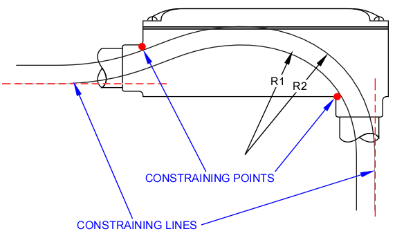
Yes, but look at the diagram as to how R1 and R2 are "formed". They are both tangential to 90?-to-body conduit. That would only be true of a cable that completely fills the I.D. of the conduit. We all know fill requirements are 1 @ 53%, 2 @ 31%, and >2 @ 40% of cross-sectional area. A cable smaller than the I.D. of the conduit would be more relaxed on entry, as in the lower depiction I posted earlier.
 
Yes, but look at the diagram as to how R1 and R2 are "formed". They are both tangential to 90?-to-body conduit. That would only be true of a cable that completely fills the I.D. of the conduit. We all know fill requirements are 1 @ 53%, 2 @ 31%, and >2 @ 40% of cross-sectional area. A cable smaller than the I.D. of the conduit would be more relaxed on entry, as in the lower depiction I posted earlier.
Annotated depiction....

LBbendradius2.gif
 
Wouldn't manufacturers requirement for greater bending radius would override that for multiconductor cables?
Of course. For LV cable, the concerns are usually the stress on the insulation and the deformation of the conductor. As you know, for MV cable and HV cable there is more stuff in the sandwich to get squished, punctured, tortured, and violated and it is more tenderer (also true for some comm cable, fiber, etc).
 
That's just ludicrous compared to traditional in-the-field practice. Traditional in the sense of what has been done for at least a half century... with very little if not no consequence.
Traditional for whom (or is it "who?"... I never can remember)? If you violate the minimum radius then it is violated. The violation length, frequency, or lack of available violation evidence does not negate the violation.

Violate the radius with fiber and you will probably have evidence sooner than later. They make bodies with radius supports for fiber and such.

Did you see and understand the rationale of my earlier post (Post #33)? I remain highly suspect of the "R" value determinations.
The table uses the the short distance (bottom of horizontal conduit and left of vertical conduit) but if you can work it out in more precise detail and not over-bend the cable then that might allow you to use a smaller conduit body in some cases. Perhaps a table of all scenarios you plan to encounter on the job would be handy to have so you could save a few bucks.

It might be an interesting exercise but don't feel like modeling in CAD at the moment. Maybe even a mathematical solution would be interesting but I don't feel like that either. I'm too lazy today.
 
Yes, but look at the diagram as to how R1 and R2 are "formed". They are both tangential to 90?-to-body conduit. That would only be true of a cable that completely fills the I.D. of the conduit.
Or forced against the short distance walls, which could happen with multiple cables. But for one cable, your point is certainly valid.

We all know fill requirements are 1 @ 53%, 2 @ 31%, and >2 @ 40% of cross-sectional area. A cable smaller than the I.D. of the conduit would be more relaxed on entry, as in the lower depiction I posted earlier.
That is certainly a valid point for a single cable but might be a stretch for multiple cables unless someone put in a whole lot of effort to make sure the cables were oriented just right.
 
Last edited:
Traditional for whom (or is it "who?"... I never can remember)? If you violate the minimum radius then it is violated. The violation length, frequency, or lack of available violation evidence does not negate the violation.
Traditional as in existing installations and for electricians in the field that actually install the stuff :D

I can tell you from experience and observation that [most] electricians in the field do not bother with determining the bending radius. The conduit body used is the same trade size as the conduit. It is extremely rare to see an upsized conduit body.

Violate the radius with fiber and you will probably have evidence sooner than later. They make bodies with radius supports for fiber and such.
Likely so.

The table uses the the short distance (bottom of horizontal conduit and left of vertical conduit) but if you can work it out in more precise detail and not over-bend the cable then that might allow you to use a smaller conduit body in some cases. Perhaps a table of all scenarios you plan to encounter on the job would be handy to have so you could save a few bucks.
Unless the powers that be on the project take first hand interest, that's not going to happen. I have worked on power plant projects that the engineers enumerated all pieces of conduit runs, just short of actual cut lengths of conduit. Even then, I never saw an upsized conduit body spec'd.

It might be an interesting exercise but don't feel like modeling in CAD at the moment. Maybe even a mathematical solution would be interesting but I don't feel like that either. I'm too lazy today.
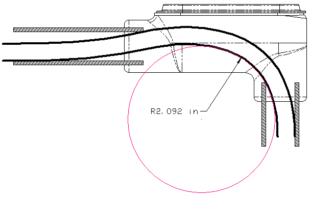
Here's one I did in CAD.

LBbendradius3.gif


The LB was downloaded from Cooper's website. Everything to scale: 3/4" Form 7 LB, 3/4" GRC crosssection positioned to max engagement depth, cable .49" diameter as the 3C/#12 in this thread, cable path simulated with a spline.

Yeah, if it's up to me to develop a math solution, everyone is going to be waiting for a long time :happyyes:
 
It is extremely rare to see an upsized conduit body.
I suspect that is because usually you have a bunch of small wires inside and the bending radius was not close to being violated. However, if someone had a big cable instead, and did not upsize to prevent a bending violation, then they messed up. I would expect the professionals here know better than to do that.

Unless the powers that be on the project take first hand interest, that's not going to happen. I have worked on power plant projects that the engineers enumerated all pieces of conduit runs, just short of actual cut lengths of conduit. Even then, I never saw an upsized conduit body spec'd.
But did they have a single cable or a bunch of little cables? I would expect a bunch of little cables, otherwise: shame, shame. I don't think they would get away with that at a nuke plant, not for long anyway.

Here's one I did in CAD.
Works for me. Since the OP asked about a tee, and you seem to be in the mood, how about a tee model for the OP application?

Yeah, if it's up to me to develop a math solution, everyone is going to be waiting for a long time :happyyes:
Me too. Unless someone feels like paying for it, I'm not feeling it.
 
Traditional as in existing installations and for electricians in the field that actually install the stuff :D

I can tell you from experience and observation that [most] electricians in the field do not bother with determining the bending radius. The conduit body used is the same trade size as the conduit. It is extremely rare to see an upsized conduit body.


Likely so.


Unless the powers that be on the project take first hand interest, that's not going to happen. I have worked on power plant projects that the engineers enumerated all pieces of conduit runs, just short of actual cut lengths of conduit. Even then, I never saw an upsized conduit body spec'd.


Here's one I did in CAD.

LBbendradius3.gif


The LB was downloaded from Cooper's website. Everything to scale: 3/4" Form 7 LB, 3/4" GRC crosssection positioned to max engagement depth, cable .49" diameter as the 3C/#12 in this thread, cable path simulated with a spline.

Yeah, if it's up to me to develop a math solution, everyone is going to be waiting for a long time :happyyes:

Your drawing solution is false as it does show the conduit instead of the internal casting wall of the condulet body, which will reduce the available bending space.
 
Your drawing solution is false as it does show the conduit instead of the internal casting wall of the condulet body, which will reduce the available bending space.
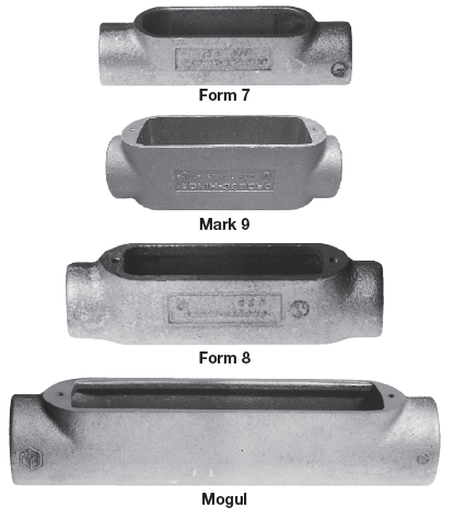
True :ashamed:. Many (most) have a internal rim that serves as a "bushed" entry, some more constricting than others. But FWIW, I wanted to use a Form 8 but couldn't locate a downloadable dwg without becoming a member to the websites having one available.

Conduitbodyforms.gif
 
I suspect that is because usually you have a bunch of small wires inside and the bending radius was not close to being violated. However, if someone had a big cable instead, and did not upsize to prevent a bending violation, then they messed up. I would expect the professionals here know better than to do that.

But did they have a single cable or a bunch of little cables?
I'm referring to Type TC cables. Could start the run with one to many. Latter type runs "tree" out as they are distributed. At a "tee' for example, conduit body the size of entry conduit size, then exit ports RE'd to smaller size conduit.

FWIW, most conduit sizes are spec'd by the engineering drawings... but they don't [in my experience] spec' the conduit body size. What gets put in the run is the size that matches the largest conduit entry. The cables usually aren't present to obtain diameters when the conduit is being installed.

All done by professionals. I'm not making excuses, just telling you how it is.

... I don't think they would get away with that at a nuke plant, not for long anyway.
Likely not!!!

... Since the OP asked about a tee, and you seem to be in the mood, how about a tee model for the OP application?
If I feel rambunctious in a while... doubting it at present ;)

...and see my reply to Laszlo.

Aside from that, a tee is more restrictive on the bending radius, but it is usually indicative of at least two cables in the run, so the fill requirement is reduced to 31% for 2, and 40% for 3 or more. A step closer to the small wires scenario you mentioned earlier. The relative diameter of a single cable to the conduit & body size betters the likelihood of meeting the bending radius requirement.
 
Last edited:
True :ashamed:. Many (most) have a internal rim that serves as a "bushed" entry, some more constricting than others. But FWIW, I wanted to use a Form 8 but couldn't locate a downloadable dwg without becoming a member to the websites having one available.

Yeah, I believe I was able to download from the C-H site a while ago, that's how I remembered. I think all have the internal rim. Killark, Adalet amd C-H fer sure.

I have been figthing this windmill now for decades so I have prepare various cross-sectional fitting drawings with single and multiple tray cables since most of the time it is a power and a control TC-ER cable in the same conduit and one splits off at the control station. Maybe I fond those drawing when I get to my office on Monday. I prepared those years ago and several computer uprgades ago. I saved them - if I recall correclty - to disk and I don't remember transfering them to the hard drive. My current machine does not even have a disk reader.
 
Yeah, I believe I was able to download from the C-H site a while ago, that's how I remembered. I think all have the internal rim. Killark, Adalet amd C-H fer sure.

...
I can't remember the manufacturer, but as I recall (which is not reliable in this matter ;)) there are some aluminum models which do not.
 
... Since the OP asked about a tee, and you seem to be in the mood, how about a tee model for the OP application?
Aside from that, a tee is more restrictive on the bending radius, but it is usually indicative of at least two cables in the run, so the fill requirement is reduced to 31% for 2, and 40% for 3 or more. A step closer to the small wires scenario you mentioned earlier. The relative diameter of a single cable to the conduit & body size betters the likelihood of meeting the bending radius requirement.
Assuming there will be two cables when using a tee, the minimum size conduit to meet fill requirements will be 1-1/4" for a combination of two 3C/#12, or one 3C/#12 and one 3C/#14... diameters as posted by OP'er. ...

Your drawing solution is false as it does show the conduit instead of the internal casting wall of the condulet body, which will reduce the available bending space.

... Many (most) have a internal rim that serves as a "bushed" entry, some more constricting than others. ...
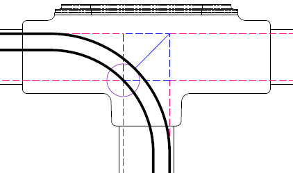
I think a reasonable assumption is the cable will have at least the volume of cylindrical projections of the inside cross section of the conduit to the extent of their intersection... right?

The following depiction uses that theory with a 1-1/4" Form 7 Tee downloaded from Cooper, extraneous blend lines removed for clarity.

LBbendradius4.gif


Considering the "construction" entities in the depiction, we now have a basis for a "simple" formula. The solid blue line will always be √2 ? 1 ≈ 0.4142 times the outside bend radius. A full diagonal of the blue dashed square will be the conduit I.D. ? √2, which is also equal to the cable diameter plus the length of the solid blue line. Hence we have:

(I.D. ? √2 ? Cable O.D.) = length of solid blue line (SBL)
SBL ? (√2 ? 1) = outside bending radius (OBR)
OBR ? Cable O.D = inside bending radius (IBR)

In combined form:

(I.D. ? √2 ? Cable O.D.) ? (√2 ? 1) ? Cable O.D = IBR

Thus:

IBR = (1.394 ? √2 ? 0.49) ? (√2 ? 1) ? 0.49 = 3.09"

...and that is the exact [rounded] value of the inside radius in my CAD drawing.

Note this formula has no bearing on the conduit body's actual dimensions (other than the assumption the "bushed" entry is not smaller than the conduit I.D.)... and the maximum bending radius for an LB could actually be slightly larger than this calculated value.
 
Traditional as in existing installations and for electricians in the field that actually install the stuff :D

I can tell you from experience and observation that [most] electricians in the field do not bother with determining the bending radius. The conduit body used is the same trade size as the conduit. It is extremely rare to see an upsized conduit body.


Likely so.


Unless the powers that be on the project take first hand interest, that's not going to happen. I have worked on power plant projects that the engineers enumerated all pieces of conduit runs, just short of actual cut lengths of conduit. Even then, I never saw an upsized conduit body spec'd.


Here's one I did in CAD.

LBbendradius3.gif


The LB was downloaded from Cooper's website. Everything to scale: 3/4" Form 7 LB, 3/4" GRC crosssection positioned to max engagement depth, cable .49" diameter as the 3C/#12 in this thread, cable path simulated with a spline.

Yeah, if it's up to me to develop a math solution, everyone is going to be waiting for a long time :happyyes:

/​
? 1 " l.R?7


Attachments

  • LB27_1in.pdf
    20.6 KB · Views: 1
Last edited:
Considering the "construction" entities in the depiction, we now have a basis for a "simple" formula. The solid blue line will always be √2 ? 1 ≈ 0.4142 times the outside bend radius. A full diagonal of the blue dashed square will be the conduit I.D. ? √2, which is also equal to the cable diameter plus the length of the solid blue line. Hence we have:

...
Looks good. :thumbsup: I knew you were in the mood.
 
Status
Not open for further replies.
Top