Issue wiring a 6-lead single phase motor to an 8-pin control relay

Namcy

Member
Location
USA
Occupation
Maintenance Technician
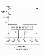
I have tried to wire a 6-lead single phase motor to an 8-pin control relay. I could not attach the pictures, because it is complicated process just to do so in this forum, where I am new, as compared to others. Maybe someone could tell me how to do that. I have connected the terminals ( T1, T2, T3, T4, T5, T8 ) coming from the motor and the wires labelled 513, 514, 515 and 2M as follows:

Wire nut 1 : T2(White) + T4(Yellow) + T5(Black), (514) + (2M) joined together.

Wire nut 2 : T1(Blue) + T3(Orange) + T8(Red) + (513) + (515) joined together.

However the circuit breaker CB503 keeps tripping and the associated fused has blown. I would like to know what might be the issue with my wiring.

Thank you
 

TwoBlocked

Senior Member
Location
Bradford County, PA
Occupation
Industrial Electrician
I am familiar with the T1 through T8 wires, but not the 513 through 2M. Are these to the relay? And what voltage are you applying and to which wires. Finally, how are you energizing the relay?
 

Namcy

Member
Location
USA
Occupation
Maintenance Technician
Really need the diagram. An easy way to post it is to use the windows clip function and just paste from clipboard into a new post.
Thank you for your answer. I have tried attaching the pictures to my post, but I keep getting the message "Image cannot be loaded from the passed link". Please do you know how to overcome that issue?
 

Little Bill

Moderator
Staff member
Location
Tennessee NEC:2017
Occupation
Semi-Retired Electrician
Thank you for your answer. I have tried attaching the pictures to my post, but I keep getting the message "Image cannot be loaded from the passed link". Please do you know how to overcome that issue?
Try taking a picture of the diagram with your phone and post the image here.
 

Namcy

Member
Location
USA
Occupation
Maintenance Technician
Try taking a picture of the diagram with your phone and post the image here.
Thank you for your answer. Honestly, maybe it is because I am a new member, but I have tried every single method I know of, and used successfully on other forums with no problem, to attach the images along with my post, to no avail. Very frustrating
 

Namcy

Member
Location
USA
Occupation
Maintenance Technician
You could try reducing the file size of your picture.

Picture or not - What are leads 513, 514, 515, 2M for? I would leave them out and try the motor.
Thank you for your answer. Without a picture, it would be difficult to explain. These are connexions inside the control relay. All the wires I mentioned in my initial post are necessary for the wiring. There is nothing to be left out. This is not an option.

Honestly, maybe it is because I am a new member, but I have tried every single method I know of, and used successfully on other forums with no problem, to attach the images along with my post, to no avail. Very frustrating. I do not think the size of the images is the issue. I have uploaded the same images on another forum with no problem.
 

Namcy

Member
Location
USA
Occupation
Maintenance Technician
At last!!!! Thank you very much indeed to whoever lifted the restrictions on my account, thus allowing me to attach pictures to my post. Here are the pictures related to my initial post.
 

Attachments

  • The nameplate of the motor.jpg
    The nameplate of the motor.jpg
    39.7 KB · Views: 43
  • Wiring diagram of the control relay.jpg
    Wiring diagram of the control relay.jpg
    13.6 KB · Views: 42

Namcy

Member
Location
USA
Occupation
Maintenance Technician
It may have to do with you being a new member. Don't give up yet. Wait 30 minutes and try again.
Thank you very much indeed for lifting the restrictions on my account. I am now able to attach pictures to my posts. I have created a new post for my initial issue.
 

Namcy

Member
Location
USA
Occupation
Maintenance Technician
Really need the diagram. An easy way to post it is to use the windows clip function and just paste from clipboard into a new post.
Attached are the diagrams. Thank you
 

Attachments

  • The nameplate of the motor.jpg
    The nameplate of the motor.jpg
    39.7 KB · Views: 5
  • Wiring diagram of the control relay.jpg
    Wiring diagram of the control relay.jpg
    13.6 KB · Views: 7

Namcy

Member
Location
USA
Occupation
Maintenance Technician
I am familiar with the T1 through T8 wires, but not the 513 through 2M. Are these to the relay? And what voltage are you applying and to which wires. Finally, how are you energizing the relay?
Thank you for your answer. Attached are the pictures of the wiring diagrams.
 

Attachments

  • The nameplate of the motor.jpg
    The nameplate of the motor.jpg
    39.7 KB · Views: 8
  • Wiring diagram of the control relay.jpg
    Wiring diagram of the control relay.jpg
    13.6 KB · Views: 8

Namcy

Member
Location
USA
Occupation
Maintenance Technician
Is this a new motor replacement.
Post pic of old motor diagram.
Looks like you have a single phase reverse relay.
The motor is the one currently in place and it was operated manually to move another equipment, which is the issue I am trying to resolve.
 

Tulsa Electrician

Senior Member
Location
Tulsa
Occupation
Electrician
Red to 514
Black to 515
Blue and orange to 513
White and yellow to w-2

If the direction in backward
Switch black and red
Red to 515
Black to 514


This for 115 volt as shown
 

Namcy

Member
Location
USA
Occupation
Maintenance Technician
The motor is the one currently in place and it was operated manually to move another equipment, which is the issue I am trying to resolve.
I do not have an old motor diagram. All the information available to me has been provided in my post. I am just trying to understand the reason my wiring keeps blowing the fuse protecting the circuit even though it seems I did it correctly according to the electrical diagram I was provided.
 

Tulsa Electrician

Senior Member
Location
Tulsa
Occupation
Electrician
The relay is a motor direction revealing relay. Should have a timer in line to keep for reversing to soon and damaging relay and motor. Make sure it stops completely before reversing.
 

Namcy

Member
Location
USA
Occupation
Maintenance Technician
Red to 514
Black to 515
Blue and orange to 513
White and yellow to w-2

If the direction in backward
Switch black and red
Red to 515
Black to 514


This for 115 volt as shown
Thank you for your answer. However, I am confused because the wiring diagram on the motor's nameplate stipulates that, for low voltage, to also connect (blue+orange +red) and (black+yellow+white) respectively TOGETHER. To me your answer seems to insinuate that the red white wire should be connected to 514 and the black wire to 515, but separately. Am I mistaken in my interpretation of the wiring in the nameplate?
Red to 514
Black to 515
Blue and orange to 513
White and yellow to w-2

If the direction in backward
Switch black and red
Red to 515
Black to 514


This for 115 volt as shown
The relay is a motor direction revealing relay. Should have a timer in line to keep for reversing to soon and damaging relay and motor. Make sure it stops completely before reversing.
 
Top