KWH metering of (15) 20A circuits by one meter

Status
Not open for further replies.

victor.cherkashi

Senior Member
Location
NYC, NY
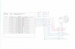
There is (15) 20A power and lighting circuits belong to tenant in house panel which I would like to meter the KWH.

My plan is to install KWH meter with remote current transformers in metal enclosure. All circuits of phase-A go thru 1st C/T, all circuits of phase-B go thru 2nd C/T, all circuits of phase-C go thru 3rd C/T.

I say it should work fine, but some of my colleagues say they are not sure about correct KWH metering.

What is you opinion? Does anyone see a possible problem with the correct KWH metering?

Thank you in advance
 

winnie

Senior Member
Location
Springfield, MA, USA
Occupation
Electric motor research
When multiple conductors are fed through a current transformer, then the CT measures the sum of all the currents.

There might be some small error terms introduced by the conductors being spread out in the window rather than passing directly through the center, but the basic principal of what you describe is sound.

-Jon
 

kwired

Electron manager
Location
NE Nebraska
If it were 120/240 single phase system (180 degree phase angle) you could even put all L1 through in one direction and all of L2 through in opposite direction and it would work on a single CT.

Can't do that with three phase system (120 degree phase angle) though.
 

Hv&Lv

Senior Member
Location
-
Occupation
Engineer/Technician
That’s fine as long as you use a 9S meter.
most now will give you the phasor angles if you use a magnet and set them in diagnostic mode.
I highly recommend you do that. Check your phase angles for voltage and currents after its metered.
 

victor.cherkashi

Senior Member
Location
NYC, NY
If it were 120/240 single phase system (180 degree phase angle) you could even put all L1 through in one direction and all of L2 through in opposite direction and it would work on a single CT.

Can't do that with three phase system (120 degree phase angle) though.

The system is 120/208V, 3-Phase, 4-Wire
The preliminary selection of meter is E-Mon "E20-208100-JKIT"
 

ron

Senior Member
It should be fine as long as the conductor lengths are sufficiently long enough to make it through the common phase CT's and you run them through all in the same direction.
 

gar

Senior Member
Location
Ann Arbor, Michigan
Occupation
EE
191211-1510 EST

You need to study circuit theory, and what average power means.

One common knowledge comment from the Internet is :
"If a 3-phase system has four wires, it is necessary to use three wattmeters, unless it is known that the system is balanced and therefore no current is flowing in the neutral wire. For any balanced N wire system it is necessary to use N − 1 wattmeters to measure the total power." Almost correct, but not quite. N-1 applies in an unbalanced system if meters are correctly connected.

More references:
http://ecelabs.njit.edu/ece494/lab1.php
https://en.wikipedia.org/wiki/Blondel's_theorem

This N-1 is someting I was taught about 70 years ago.

.
 

gar

Senior Member
Location
Ann Arbor, Michigan
Occupation
EE
191211-1946 EST

victor.cherkashi:

Looks OK.

I assume this is a 3 phase wye. You will need the three voltages to be from the three lines to neutral, and correctly associated. If the source was delta, then it would be necessary to synthesize a neutral voltage point, or use only two current transformers, and use the one phase without the current transformer as the voltage reference for the two voltage measurements.

.
 
Status
Not open for further replies.
Top