jaggedben
Senior Member
- Location
- Northern California
- Occupation
- Solar and Energy Storage Installer
Usually when I engage in debates (or perhaps, 'debates'?) on this forum I tend to moderate my position over time. But in this case I'm starting to feel the opposite about it.
Ingenieur, Besoeker, (mivey?):
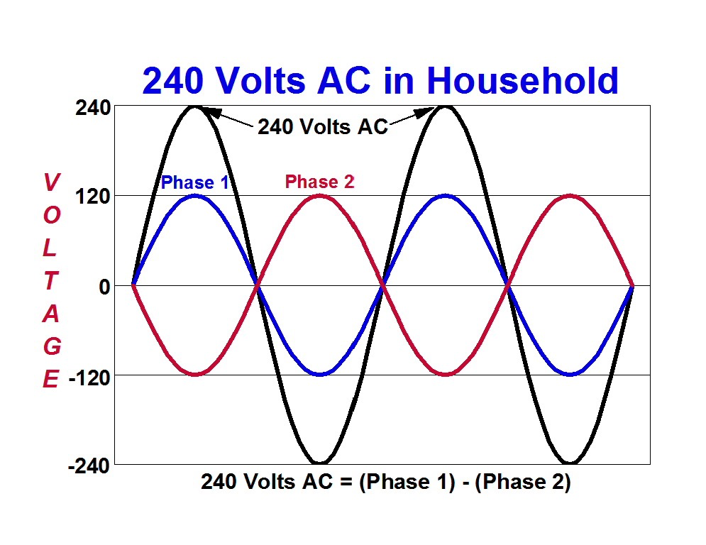
It's been pointed out that in the physical world there are multiple ways to derive a 120/240V AC source with a waveform(s) resembling a sign wave.
Can you not agree that, for most such cases, multiplying the instantaneous voltage L1-N by -1 is a more reliable way to predict the simultaneous, instantaneous voltage L2-N than employing any vector function?
For a transformer source derived from a single primary waveform, that's true if there's any distortion or interruption of the primary.
As gar pointed out, for two generator windings attached to the same shaft at 180deg, if something disrupts the shaft motion, that's true.
The only common exception I'm unsure about would be two inverters that are synced electronically. That depends on the syncing algorithm. However, I suspect that employing a vector function would still not be more reliable than multiplying by -1.
Ingenieur, Besoeker, (mivey?):
It's been pointed out that in the physical world there are multiple ways to derive a 120/240V AC source with a waveform(s) resembling a sign wave.
Can you not agree that, for most such cases, multiplying the instantaneous voltage L1-N by -1 is a more reliable way to predict the simultaneous, instantaneous voltage L2-N than employing any vector function?
For a transformer source derived from a single primary waveform, that's true if there's any distortion or interruption of the primary.
As gar pointed out, for two generator windings attached to the same shaft at 180deg, if something disrupts the shaft motion, that's true.
The only common exception I'm unsure about would be two inverters that are synced electronically. That depends on the syncing algorithm. However, I suspect that employing a vector function would still not be more reliable than multiplying by -1.