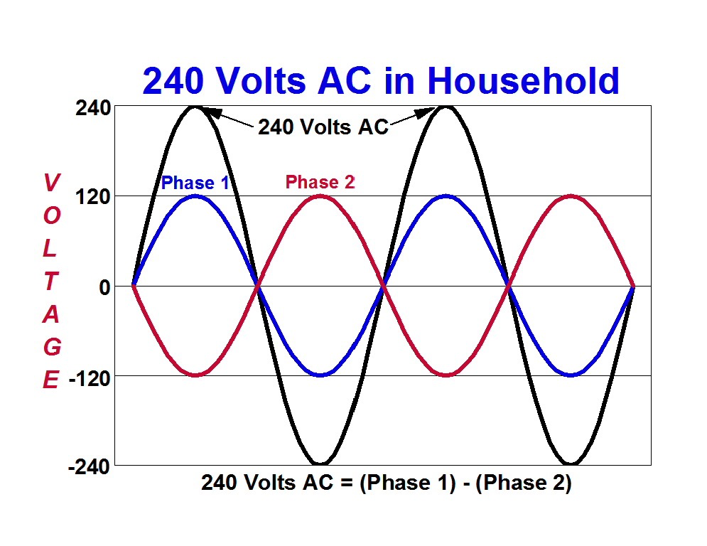
May I ask a question about the single vs two phase stuff

Status
Not open for further replies.
The distinction is clearer when you use two waveforms to run one circuit. Like when we only use the positive halves of the two waves like we do with a 2-diode full-wave rectifier. This is a circuit that makes use of the 180d difference.

Most other circuits do not utilize more than one waveform from the selection available.

When you only use one waveform, it is hard to appreciate the fact that the transformer can supply two waveforms with a 180d displacement. You could build these 180d displacements using a gen-set but why do that when the transformer can substitute?

Anyway, if you focus on the positive halves of the waveforms, you can see the work is done with a 180d displacement. An example would be the charging of a VFD using the positive pulses produced 180d apart.

Again, we could provide these 180d positive pulses from a set of two 180d displaced voltages using a common generator shaft with 180d displaced windings but one should be able to recognize that the center-tapped transformer can also supply this set of voltages.

Until you can step back and recognize that multiple sets can ultimately map to the same physical space, it is hard to see that they lay on top of each other but still exist.

As an example of looking beyond what may appear on the surface, you may or may not be aware of n-th roots. Just because you found one solution to an equation does not mean you found them all.

I agree, but 180* does not provide continuous over all power.
 
Actually there are three but only two of equal magnitude.

I have spent too many hours in labs to go along with that.

ok - just wondered why you believed it. I'm going to propose that theoretically there can be only one 60 hz signal, therefore if you've seen anything more than that, its a product of your interference ( ie scope not correctly corrected, settings wrong, etc. ) We'll have to agree to disagree on this point
 
ok - just wondered why you believed it. I'm going to propose that theoretically there can be only one 60 hz signal, therefore if you've seen anything more than that, its a product of your interference ( ie scope not correctly corrected, settings wrong, etc. )
It is a product of what signals we extract from the system and what the system can supply. If I extract only one signal then that is all we have supplied. If I extract three signals then that is what we have supplied.

Nothing magical happens. The signals are actually extracted and that is what the system can supply. The signals do indeed exist, physically and theoretically.

The discussion is about the signals we extract because that is what we are ultimately using.

To put it simply: there are two "flux events" that occur inside the transformer. These occur across two windings so we have four "event results". These are there waiting to be used however we want.

We can use that to either extract two waveforms with the same positive peak (netting two positive peaks and two negative peaks together) or two waveforms with positive peaks at a 180d displacement. Call these the 120v voltages.

We could also just take one larger waveform that combines the four "event results" to produce one larger waveform with two larger "event results" (a larger combined positive and negative peak). Call this the 240v voltage.

That is what Steinmetz was talking about. If you combine the two smaller phases in a 180d system by taking one to be the return of the other, you can get a single larger phase. But the two smaller phases do physically exist in the 180d system.

Anyway, for 180d, we extract one waveform starting at the first flux event and one waveform starting at the second flux event. This is the center-tap reference point.

There is nothing untoward happening. We are simply making use of electrical and physics fundamentals that say we get to define the voltage. It is a fundamental principle.

The reference is a choice and either way is correct. It is really that simple.

We'll have to agree to disagree on this point
OK
 
Thank you. I've been told that I understand theory better than the average electrician.

Engineers have been known to over-think things.

Although Mivey seems to disagree with some of my assertions, I stand by them.

never thought it was bad to 'over' think something
yes, the time comes to cut bait of fish, but I do not think you can 'over think' anything, except perhaps this topic :lol:
 
Last edited:
Ok - why do you continue to say there are two wave forms?

When the primary completes one cycle, the secondary completes one cycle - nothing more. From l1 to l2 there is only one wave form, another wave is not create because we tap into coil midway. the only way to get additional wave is to have additional primary out of phase with first primary

:?

because there ARE 2 waveforms relative to common/neut
they combine into single phase

the same applies to 3 phase
when a primary phase completes a cycle the corresponding sec phase completes a cycle
that proves nothing
 
ok - just wondered why you believed it. I'm going to propose that theoretically there can be only one 60 hz signal, therefore if you've seen anything more than that, its a product of your interference ( ie scope not correctly corrected, settings wrong, etc. ) We'll have to agree to disagree on this point

well no, you are wrong on this point
split-phase, ie, divide one in two
if you have a scope, observe polarity and use 2 probes, L1-n and L2-n, you WILL get 2 waveforms 180 deg out of phase
that is incontrovertible fact, no matter what spin is applied
 
Okay, given I started this up again, let me ask for a recap. This is what I think has been said.

We do not have two phases 180 degrees apart in time. We have one phase, that when viewed from the center tap, has one windings polarity inverted (multiply by -1). This is indistinguishable from a 180 phase shift in time, as long as we are looking at a pure sine wave. Once we have loads that cause distortions/harmonics then the difference, between inverted polarity and 180 degree phase shift, becomes apparent.

Close enough?

I agree. :D
 
180726-0849 EDT

buffalonymann:

A voltage is measured between any two points of your choice. These two points can become one, but to know what the voltage difference is at an infinitesimally small distance you must study how the voltage changes as the distance approaches zero.

On the other hand a voltage gradient is measured at a point.

Current is also measured at a point.

You can select any point to be your voltage reference point. Often times this is ground, earth, or common. But there is no reason it can not be the +12 V terminal of a battery that I use as a reference to measure the output impedance of a DC regulated supply.

.
 
well no, you are wrong on this point
split-phase, ie, divide one in two
if you have a scope, observe polarity and use 2 probes, L1-n and L2-n, you WILL get 2 waveforms 180 deg out of phase
that is incontrovertible fact, no matter what spin is applied
If, however, you probe L1-N and then N-L2, then you would consider the two to be in phase, correct? Keeping one probe on the center tap is a measurement choice, just as grounding that point is a design choice.

Technically speaking, because of the choice to ground the center tap, and the choicer to use the center tap as your reference (grounded probe), you're inverting the probes ads you apply them to the terminals.

If you were scoping a pair of batteries, would you keep the grounded probe on the center point between them, or move both probes, keeping the polarity consistent, with the grounded probe toward negative?

I will agree that, if I were scoping a dual-polarity DC power supply, I would keep the grounded probe on the grounded center-tap, but I would acknowledge that I'm seeing an expected polarity difference.


no, it is not a choice
the neut is the 'common' or reference or 'negative' and polarity should be observed
 
If, however, you probe L1-N and then N-L2, then you would consider the two to be in phase, correct? Keeping one probe on the center tap is a measurement choice, just as grounding that point is a design choice.
Most two channel 'scopes have a common ground terminal for each. If you want to measure the two aides of the 120-00-120 simultaneously to compare them. using the neutral as the common is the only choice.
 
It is a product of what signals we extract from the system and what the system can supply. If I extract only one signal then that is all we have supplied. If I extract three signals then that is what we have supplied.

Nothing magical happens. The signals are actually extracted and that is what the system can supply. The signals do indeed exist, physically and theoretically.

The discussion is about the signals we extract because that is what we are ultimately using.

To put it simply: there are two "flux events" that occur inside the transformer. These occur across two windings so we have four "event results". These are there waiting to be used however we want.

We can use that to either extract two waveforms with the same positive peak (netting two positive peaks and two negative peaks together) or two waveforms with positive peaks at a 180d displacement. Call these the 120v voltages.

We could also just take one larger waveform that combines the four "event results" to produce one larger waveform with two larger "event results" (a larger combined positive and negative peak). Call this the 240v voltage.

That is what Steinmetz was talking about. If you combine the two smaller phases in a 180d system by taking one to be the return of the other, you can get a single larger phase. But the two smaller phases do physically exist in the 180d system.

Anyway, for 180d, we extract one waveform starting at the first flux event and one waveform starting at the second flux event. This is the center-tap reference point.

There is nothing untoward happening. We are simply making use of electrical and physics fundamentals that say we get to define the voltage. It is a fundamental principle.

The reference is a choice and either way is correct. It is really that simple.

OK

The secondary is one coil and there are (2) flux events; the first field collapse results in current flowing from L1 to L2 and the second field collapse results in current flowing from L2 to L1. One coil = 1 current sine wave.

Example: Secondary Coil (SC) has 40 turns, each turn produces 6 volts at each flux event (FE) 40x6=240volts. Each turn produces the 6volts at the same time. You decide you want 120 volts so instead of using 40 turns of the SC you use 20 (20x6=120v) doesn't matter if you use the first 20 or the second 20, you are still utilizing very same current sine wave that is generated in the 40 turns.

The 240v sine wave is the same sine wave in both halves of the coil. All three are in phase with each other which means there is only (1) sine wave

This is why we use the motor analogy, you can't start an induction motor with single phase power because there is only one signal alone. I've notice people grumbling about the motor analogy, it blows away their hypothesis and appears to be upsetting them.
 
Most two channel 'scopes have a common ground terminal for each. If you want to measure the two aides of the 120-00-120 simultaneously to compare them. using the neutral as the common is the only choice.
I'm sorry, why can't you put the 'scope common terminal on L1, and put the two probes on N and L2? Assuming the inputs are properly isolated from the 'scope power source?

Cheers, Wayne
 
The secondary is one coil and there are (2) flux events; the first field collapse results in current flowing from L1 to L2 and the second field collapse results in current flowing from L2 to L1. One coil = 1 current sine wave.

Example: Secondary Coil (SC) has 40 turns, each turn produces 6 volts at each flux event (FE) 40x6=240volts. Each turn produces the 6volts at the same time. You decide you want 120 volts so instead of using 40 turns of the SC you use 20 (20x6=120v) doesn't matter if you use the first 20 or the second 20, you are still utilizing very same current sine wave that is generated in the 40 turns.

The 240v sine wave is the same sine wave in both halves of the coil. All three are in phase with each other which means there is only (1) sine wave

This is why we use the motor analogy, you can't start an induction motor with single phase power because there is only one signal alone. I've notice people grumbling about the motor analogy, it blows away their hypothesis and appears to be upsetting them.

they are not in phase, they are 180 deg out
the motor argument is a strawman

split-phase
ˈsplitˌfāz/
adjective
adjective: split-phase

  • denoting or relating to an induction motor or other device utilizing two or more voltages at different phases produced from a single-phase supply.

    different implies more than 1


Last edited:
Status
Not open for further replies.
Top