Mivey, I definitely know the difference between AC and DC. I only use the battery example because, being wound on a common core and driven by the same single primary waveform, the two halves of the secondary are always varying in sync.
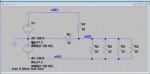
I consider two series-connected 120v secondaries and a single center-tapped 240v secondary to be identical here. At any moment, the "positive" end of one half of the secondary is connected to the "negative" end of the other at, or as, the neutral.
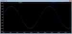
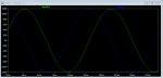
I agree that, let's say, L1 is positive-going while L2 is negative-going (and vice versa), and from the neutral's point of view, certainly appear out of phase, but as two series-connected sources that form a single source, in order to add, must be in phase.