jumper
Senior Member
- Location
- 3 Hr 2 Min from Winged Horses
Interesting........
Only in context. Only works as a comparison under ideal conditions, balanced resistive load.
Will not work under normal/real conditions.
Interesting........
Are you kidding? This whole discussion is a tangent!
Lol. Fair enough.
At some point I had hopes that some conclusions could be drawn about which mathematical functions better describe certain real world aspects of the system. But it seems no one wants to have that discussion.
OK, let's try that.At some point I had hopes that some conclusions could be drawn about which mathematical functions better describe certain real world aspects of the system.
And if you consider the vectors/waveforms as L1-N and the other as N-L2 rather the conventional......Only in context. Only works as a comparison under ideal conditions, balanced resistive load.
Will not work under normal/real conditions.
And if you consider the vectors/waveforms as L1-N and the other as N-L2 rather the conventional......
. . . which I apparently do, because it means that the center tap does not change how the secondary functions as a whole.And if you consider the vectors/waveforms as L1-N and the other as N-L2 rather the conventional......
OK, let's try that.
In the idealized system with sine wave voltages of frequency f, we have two relations that both hold: (A) VL1-N(t) = - VL2-N(t) and (B) VL1-N(t) = VL2-N(t - 1/2f). So what are the ways in which the real world differs from the idealized? Here's the start of a list:
1) Primary voltage is not a pure sine wave.
2) Primary voltage source is not infinitely stiff.
3) Secondary windings are not identical.
4) Secondary conductors have non-zero impedance
5) Secondary loads are not purely resistive.
6) Secondary loads are unbalanced.
7) Secondary loads are non-linear.
Probably there are a bunch more. Under which of those realities (taken individually) will (A) or (B) still hold?
Cheers, Wayne
120-0-120.. . . which I apparently do, because it means that the center tap does not change how the secondary functions as a whole.
Ideal series load.

Even some math.

Doesn’t change a thing.
the signing convention is wrong
if at common you have a + and - the associated v's must be opposite signs
as is you have a line shorted to ground
also the currents are both wrong as are the loads
Yeah, good. I'll hold off bringing back in generators and inverters until we've settled on answers for a single phase-primary transformer.
it's not valid
observing convention and for power to flow
v rise on source
v drop on load
i - to + on source and load

So,
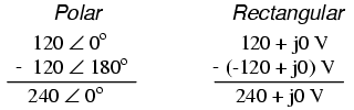
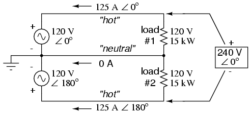
“If we mark the two sources’ common connection point (the neutral wire) with the same polarity mark (-), we must express their relative phase shifts as being 180o apart. Otherwise, we’d be denoting two voltage sources in direct opposition with each other, which would give 0 volts between the two “hot” conductors.”
Leads to this:
Two 120 V signals and and a 240V signal. 120V signals referenced to the noodle. 240V L-L.
180803-1618 EDT
Ingenieur:
In your post #732 in the circuit diagram you have corrected some errors of other drawings of this circuit, but now have added an error by reversing the + and - s on the loads.
The sum of the voltages around a loop must equal 0. Thus, the polarity signing on source and load must be the same for the same wire. With the top end of the source being labeled + this means the top end of the load must be +.
A source has a rise in voltage in going from - to + thru the source, and a load has a drop in voltage in going from + to - thru the load.
For those unhappy + and - being used in an AC, then view the drawing as labeled being for one instant of time
around the loop - to + is a positive v or rise
+vsource + vload = 0 or vsource = -vload
assume source = 10 (rise) the load = -10 (drop)
10 + (-10) = 0
???
Your drawing looked fine to me.
I gotta and read gar again. I think we got a small mix up going.
You both are saying the same thing I think.