May I ask a question about the single vs two phase stuff

Status
Not open for further replies.

winnie

Senior Member
Location
Springfield, MA, USA
Occupation
Electric motor research
Well there are times where we do use a center tapped transformer to “split phases”. We are looking to have, on one secondary winding, the original waveform, and on the other one the same exact waveform with polarity inversion. We certainly don’t want something displaced in time by 180 degrees. Doesn’t matter that this isn’t electrical distribution as transformers don’t know and obey the same laws regardless.

Keep in mind that we are using idealized mathematical descriptions to help us understand the systems in question.

For a single frequency sine wave there is absolutely no difference between inversion and a 180 degree displacement in time. None. Zilch. They are the same.

But _no_ real world system is perfectly described by a single frequency sine wave. We use a single frequency sine wave to describe lots of systems because this approximation lets us understand many important features. The single frequency sine wave _approximation_ helps us see the forest and ignore the trees.

In the limits of this approximation inversion is equal to a displacement in time.

In the real world there must be differences a time delay of 1/2 cycle and an inversion. But to even discuss these differences we have to abandon the single frequency sine wave approximation.

Once we start asking how this approximation breaks down we have to discuss the difference between a time shift and inversion.

Sometimes we do it the other way a round, a center tapped primary, AC grounded by cap with high voltage DC on it to feed two AC generators. It follows the “AC generators” are driven by previous center tapped transformer and operating in anti-phase/polarity. Under ideal conditions no AC is returned thorough the cap on center tap and DC currents are equal and opposite so core isn’t saturated.

Now what happens if one AC generator is “cut off”? What impedance does the remaining AC generator now see? Assume this generator is current limited and its transfer function is highly load dependent.

Are you describing some sort of inverter here? I don't think I am up for an analysis of the above.

Now moving back to the discussion at hand, what impedance does the source see if we only have a L1 load on our residential electrical service? Would it be different if said supply was 120/208 secondary?

With a single phase center tapped transformer, if only L1 to N is loaded, then the _single_ primary coil sees the full load.

With two legs of a three phase wye, if only L1 to N is loaded, then that load shows up as unbalanced loading on the primary. Is the primary wye or delta??

-Jon
 

LarryFine

Master Electrician Electric Contractor Richmond VA
Location
Henrico County, VA
Occupation
Electrical Contractor
For a single frequency sine wave there is absolutely no difference between inversion and a 180 degree displacement in time. None. Zilch. They are the same.
I agree with you on this 100% in the observation/measurement sense.

In the "causation" sense, it's the former; it's polarity, plain and simple.

The fact is that both observed sine waves begin simultaneously.
 

winnie

Senior Member
Location
Springfield, MA, USA
Occupation
Electric motor research
In the "causation" sense, it's the former; it's polarity, plain and simple.

The fact is that both observed sine waves begin simultaneously.

I agree that in the case of a single phase transformer the _mechanism_ is inversion, and that when (for example) the transformer is energized you would see the inversion rather than the time delay associated with a 180 degree 'shift'.

As soon as we are talking about energizing the transformer, however, we are no longer talking about single frequency sine waves.

So when we are doing our analysis based on the single frequency sine wave approximation, it makes perfect sense to use 0 and 180 degrees to talk about the two outputs.

Still a single phase transformer, still using inversion internally, and still _two_ phase angles for the purpose of analyzing the output.

-Jon
 

wwhitney

Senior Member
Location
Berkeley, CA
Occupation
Retired
For an isolation transformer with a single coil on the primary and the secondary, can someone point me to a discussion of how the secondary voltage waveform depends on the primary voltage, for an arbitrary primary voltage function? Both for an idealized transformer, and for an actual transformer?

Cheers, Wayne
 

jaggedben

Senior Member
Location
Northern California
Occupation
Solar and Energy Storage Installer
I agree that in the case of a single phase transformer the _mechanism_ is inversion, and that when (for example) the transformer is energized you would see the inversion rather than the time delay associated with a 180 degree 'shift'.

As soon as we are talking about energizing the transformer, however, we are no longer talking about single frequency sine waves.

So when we are doing our analysis based on the single frequency sine wave approximation, it makes perfect sense to use 0 and 180 degrees to talk about the two outputs.

Still a single phase transformer, still using inversion internally, and still _two_ phase angles for the purpose of analyzing the output.

Three phase doesn't have a time delay either. No matter what the setup, a 'shift' in 'degrees' never actually means a delayed start for 2nd or 3rd phases in the real world. It's all just mathematical representation that allows us to do some types of engineering as long as real world waveforms resemble ideal sine waves within acceptable tolerances.

If the 120/240 service was the only kind of electrical service that existed, and if power factor and three-phase power weren't things needing to be analyzed, no one would ever have bothered to make phasor math part of electrical engineering education. I know that's a lot of 'ifs', but the point is, inversion really is all the math you need to analyze this service with resistive loads. It doesn't 'make sense' to use phasor math if a much simpler mathematical operation produces the same result that meets your needs. If you were programming software, for example,I believe you'd need a lot less computing power using inversion. (Not very important with today's devices, but I remember the TI-88.)

Now, I totally respect the position that says 'well, I'm trained to do phasor math for all these other applications so it's just natural for me to employ it here as well.' But there is nothing ontologically privileged about phasor math. It doesn't represent what the waveforms 'are'. The 'time delay' discussion pretty much proves that.

Mind you, I think we're on the same page here. I'm just quibbling with how your putting it. I'm 'just sayin'.
 

jumper

Senior Member
Three phase doesn't have a time delay either. No matter what the setup, a 'shift' in 'degrees' never actually means a delayed start for 2nd or 3rd phases in the real world. It's all just mathematical representation that allows us to do some types of engineering as long as real world waveforms resemble ideal sine waves within acceptable tolerances.

If the 120/240 service was the only kind of electrical service that existed, and if power factor and three-phase power weren't things needing to be analyzed, no one would ever have bothered to make phasor math part of electrical engineering education. I know that's a lot of 'ifs', but the point is, inversion really is all the math you need to analyze this service with resistive loads. It doesn't 'make sense' to use phasor math if a much simpler mathematical operation produces the same result that meets your needs. If you were programming software, for example,I believe you'd need a lot less computing power using inversion. (Not very important with today's devices, but I remember the TI-88.)

Now, I totally respect the position that says 'well, I'm trained to do phasor math for all these other applications so it's just natural for me to employ it here as well.' But there is nothing ontologically privileged about phasor math. It doesn't represent what the waveforms 'are'. The 'time delay' discussion pretty much proves that.

Mind you, I think we're on the same page here. I'm just quibbling with how your putting it. I'm 'just sayin'.

See, you wanna be reasonable here, ain’t gonna work!:D

I seriously wanna explore Wayne’s earlier idea of of -1, instead of our more traditional methods of analysis of the secondary-vectors, phaser math, common reference of the neutral for a dual winding secondary, etc, gonna start a new thread in education forum, mathematics and trig only!

And another thing to talk about the way the secondary loads could impact the primary. Again a single thread on that would make sense. Windings, flux, currents, etc. To do this we need to consider the primary load’s impact on the POCO side also. This where it can really mess me up. I got no problem doing the simple primary and secondary calcs on a tranny, but distribution line calcs-nope, I am out.
 

Russs57

Senior Member
Location
Miami, Florida, USA
Occupation
Maintenance Engineer
Winnie (and others), the circuits I were describing are tube based audio. Some may feel they aren’t relevant but a transformer doesn’t know that and acts the same regardless. I think it is easier to see the 180 vs -1 point when considering music. There you have no pure sine waves and R,C, and L are always in play.

Bottom line. Voltage transformation is proportional to turns ratio. Current transformation is inversely proportional to turns ratio. Impedance is proportional to square of turns ratio. And on a center tapped transformer, the impedance from end to end is four times the impedance from center tap to either end. Does not matter what the transformer is being used for.
 

ggunn

PE (Electrical), NABCEP certified
Location
Austin, TX, USA
Occupation
Consulting Electrical Engineer - Photovoltaic Systems
Winnie (and others), the circuits I were describing are tube based audio. Some may feel they aren’t relevant but a transformer doesn’t know that and acts the same regardless. I think it is easier to see the 180 vs -1 point when considering music. There you have no pure sine waves and R,C, and L are always in play.

You know, I may have started this whole kerfuffle three threads back, and what you say is precisely the issue I brought up. There is no amount of phase shift you can apply to a complex waveform where it is indistinguishable from an inversion. I'm an old analog audio guy, myself; although most people even in audio colloquially refer to the signals in a balanced line as being "180 degrees out of phase", that's not what they are.
 

mbrooke

Batteries Included
Location
United States
Occupation
Technician
Hmmmm.

Electric-240-Volts


electric-208-volts


Both are types of common single phase services.

Math works both set ups. Two signals combined to create a larger one.:angel:


Where did you get this? This is gold to me.
 

LarryFine

Master Electrician Electric Contractor Richmond VA
Location
Henrico County, VA
Occupation
Electrical Contractor
Winnie (and others), the circuits I were describing are tube based audio. Some may feel they aren’t relevant but a transformer doesn’t know that and acts the same regardless. I think it is easier to see the 180 vs -1 point when considering music. There you have no pure sine waves and R,C, and L are always in play.
I, too, am familiar with audio and the center-trapped transformer used as a phase splitter to drive a push-pull output stage by a single-ended intermediate stage. If you think about it, this truly is a matter of signal inversion, and not a timing offset/delay.
 

Adamjamma

Senior Member
Sir Besoeker,
would the 208 volt diagram be like the three phase commercial I am learning for bs7671 training? It looks pretty. But the 240 diagram is what I was taught in 80s... maybe that is why I am having some of the problems visualizing the phase numbers here..lol
 

Besoeker

Senior Member
Location
UK
Hmmmm.

Electric-240-Volts


electric-208-volts


Both are types of common single phase services.

Math works both set ups. Two signals combined to create a larger one.:angel:
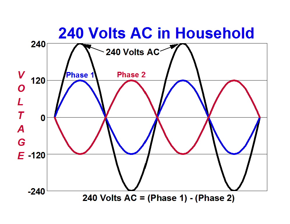
The 120, the 240, the 208 Volts are RMS values, not peak as shown on the waveforms in the diagrams.
 

Russs57

Senior Member
Location
Miami, Florida, USA
Occupation
Maintenance Engineer
Larry and ggunn, you would think that would put the whole 180 verus -1 one thing to rest. After all, how can that "phase splitter" transformer operate any differently than the transformer supplying 120/240 power to our homes in USA? It is inversion. Doesn't matter if math says it is the same under ideal conditions. Yet some stick to the 180 notion. Doesn't help that audio guys say "180 out of phase". Clearly they know the difference when they are wrapping feedback around things, using compensation networks, and worrying about poles and zeros.

Now someone made a comment about there not actually being any "time shift" with three phase. I'm picturing a rotating generator shaft and having a little problem with that comment. Might be a chance for me to learn something more out of this thread.
 
Status
Not open for further replies.
Top