More fallacious grounding

Status
Not open for further replies.
A ground rod farther from the substation does not have a higher ohm value to the substation ground. A unigrounded system does not have a ground rod distant from the substation. So the transient impedance from each individual transmission line to ground will be essentially the wire impedance of that transmission line, as part of the multiphase set, all the way back to the substation.

Then why does the real world prove otherwise?
 
https://en.wikipedia.org/wiki/Electrical_reactance


i know pretty much nothing about distribution design or theory, but i'm visualizing CEMF and no to little cancelling effect due to the distance between the wires way up on the pole and the ground(during ground fault). i keep thinking of how you are supposed to keep circuit conductors routed with each other and close in a cabinet to mitigate any inductive heating and needing the egc with the circuit conductors, like i stated before. that's the only difference i'm seeing in the schemes. it doesn't change the resistance of earth from zero.


Its true, but should not limit current to such a significant degree.


The earth itself is zero ohms from what Mike Holt has said. (If I remember right, it was in one of his videos)
 
so are you saying the ground fault current would be the same on a uniground as it would a multi grounded neutral system at say 20 miles(long distances)?


thanks, just interested, not arguing
I am not sure..... It would potentially be different if there is a grounding transformer with an earth grounded wye point at the end, but that would not be unigrounded.

Sent from my XT1585 using Tapatalk
 
A distribution system where the secondary neutral is connected (bonded) to the substation ground grid, but no multi grounded neutral is brought out of the substation and run along the poles. Hence uni, only one location. Only 3 wires (Phase A, B, C) are up on the pole.


In some 2400/4160Y system out in cali there is a 4th neutral run along the poles but its 100% insulated from earth. So technically that too would count as uni grounded.


Here is a pic of a substation "ground grid"


IMG_0006_zps3ea01d61.jpg


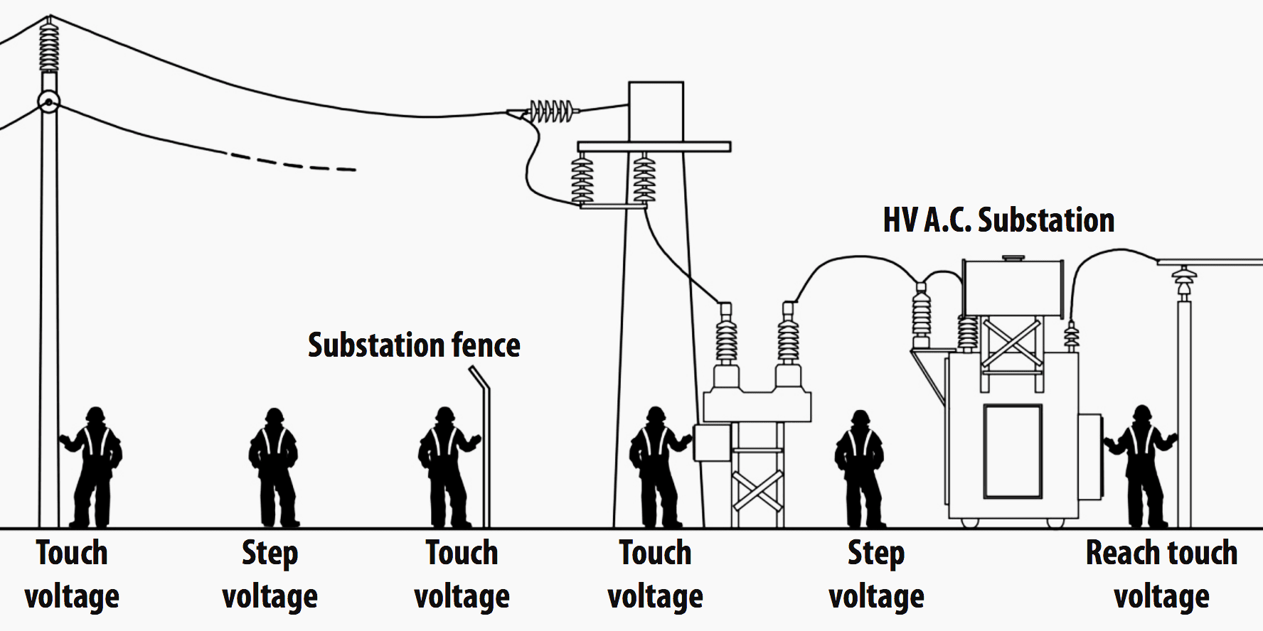
Page 9 of what it does, mainly to reduce voltage potential during faults :


https://ccaps.umn.edu/documents/CPE...ts/2017/TutIIISubstationGroundingTutorial.pdf


touch-step-voltages-around-substation.png


..............................................................................................


The thing is, and where I must admit my knowledge ends as I can not explain it-


If I have a 7.2/12kv fault to a 25 ohm ground rod 1/4 of a mile from the substation the current will be higher then if I had a fault on the same line 20 miles from the substation on an identical 8 foot 25 ohm ground rod.


However, grounding theory (among others) contradicts this by saying only the resistance of the ground rod (25 ohms) and the substation ground grid (1 ohm) would matter as the earth itself has a resistance of 0 ohms given all the infinite parallel paths which exist.


Theory says that at both 1/4 of a mile and 20 miles the current should always be 276 amps (excluding the impedance of the phase wire of course)


Yet in reality 1/4 of a mile may produce 200amps, while 20 miles down line only 5 amps.


:?:dunce::?


As such a fault at the 20 mile point will cause the phase to ground voltage to rise requiring phase-phase rated insulators and lightning arrestors.

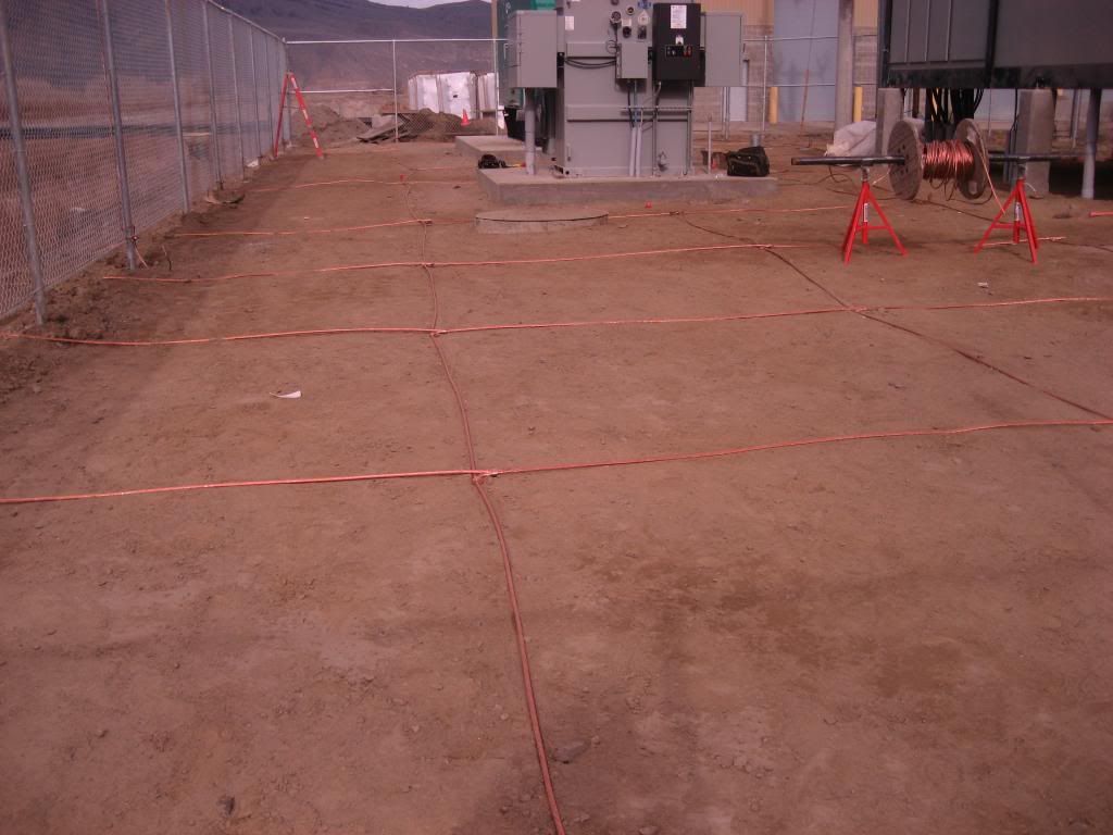
so....i just gotta ask...am I looking at one huge poco MBJ?:?~RJ~
 
I did and thats what I'm talking about.


California is loaded with 3 wire unigrounded distribution systems and there are some utilities like National Grid in Massachusetts that have 3 wire 69kv transmission lines without a lightning guard or static wire.


As you move down line the 12kv distribution line insulators, bushing and lightning arrestors are sized higher and fault currents decrease the further a fault happens from the substation.
Yes. As you move out from the ground point on a uniground system the voltage during a fault approaches line-line voltage. The fault current drops because of the added impedance.
 
If I have a 7.2/12kv fault to a 25 ohm ground rod 1/4 of a mile from the substation the current will be higher then if I had a fault on the same line 20 miles from the substation on an identical 8 foot 25 ohm ground rod.


However, grounding theory (among others) contradicts this by saying only the resistance of the ground rod (25 ohms) and the substation ground grid (1 ohm) would matter as the earth itself has a resistance of 0 ohms given all the infinite parallel paths which exist.


Theory says that at both 1/4 of a mile and 20 miles the current should always be 276 amps (excluding the impedance of the phase wire of course)


Yet in reality 1/4 of a mile may produce 200amps, while 20 miles down line only 5 amps.
Theory does not say that. Theory says, and correctly models, that the Earth path has impedance. We model the soil resistivity and can indeed model the current in the Earth path. We do this using Carson's equations.

If we could run current in the whole of the Earth, we could perhaps parallel enough dirt to negate soil resistivity but it does not work that way. It tends to be a more localized phenomenon as far as Earth scale is concerned.
 
I don't have anything to provide as a reference and i'm likely completely wrong, but would the long length along with the distance between the earth and the wires be the problem. while if you had the physically close static line that would compensate with capacitance, without the static line the distance between the ground and conductors possibly wouldn't create enough capacitance? kind of like running an egc separate from the circuit conductors?
The static coupling would be weak. I could calc the values but not the moment.
 
i was just thinking there would be a difference of capacitance between MGN and Uniground, and in turn fault current characteristics, like routing an EGC separate from the circuit conductors, ground fault current would be different.
The ground current will most definitely be higher with a MGN.
 
Once again, the difference comes from the impedance of the ungrounded conductors. The earth impedance plays no role in the calculation except to the extent that it allows capacitive coupling from all lines to the earth surface.

Sent from my XT1585 using Tapatalk
The earth impedance most definitely plays a role and is in the model.
 
But why does a uni grounded system go from behaving essentially solidly grounded to ungrounded? Why would a ground rod further from the substation have a higher ohm value to the substation ground grid?
#1:
At the sub the N conductor is at the neutral point. A A-N fault drags A to the neutral point and the B-N and C-N arrestors see P/sqrt(3) volts (line-neutral).

Far away the N conductor has a large impedance that allows it to float from the neutral point. An A-N fault drags N to A and the arrestors see B-A and C-A voltage (line-line).

#2:
The earth path has impedance.
 
The earth itself is zero ohms from what Mike Holt has said. (If I remember right, it was in one of his videos)
If you parallel enough dirt you can drive the net resistance to zero but the dirt has resistivity and the net impedance we see is not zero.
 
so....i just gotta ask...am I looking at one huge poco MBJ?:?~RJ~
That is a big flat buried multi-section ground rod. The POCO uses the earth as a conductor so they really want a good connection to it (1-5 ohms or less). Electricians do not use the earth as a conductor.
 
Yes. As you move out from the ground point on a uniground system the voltage during a fault approaches line-line voltage. The fault current drops because of the added impedance.

In full agreement 100% :)


Theory does not say that. Theory says, and correctly models, that the Earth path has impedance. We model the soil resistivity and can indeed model the current in the Earth path. We do this using Carson's equations.

If we could run current in the whole of the Earth, we could perhaps parallel enough dirt to negate soil resistivity but it does not work that way. It tends to be a more localized phenomenon as far as Earth scale is concerned.


But why the impedance? The earth is so massive that the resistance should be near zero.
 
mbrooke,

Do you think if we had a copper wire as big as the earth we would get full benefit of all of that paralleled copper mass? We don't at a smaller scale do we?

The fact is the currents travel in a peculiar manner in the wire and in the earth.
 
If you parallel enough dirt you can drive the net resistance to zero but the dirt has resistivity and the net impedance we see is not zero.
The net resistance is indeed not zero, but most if not all of that resistance is the term associated with the earth electrode resistance rather than the distance to the uniground point. If the two electrodes are within each others' sphere of influence the overall resistance will be more complicated. That can lead to the appearance of the net resistance depending on the earth path length.


Sent from my XT1585 using Tapatalk
 
mbrooke,

Do you think if we had a copper wire as big as the earth we would get full benefit of all of that paralleled copper mass? We don't at a smaller scale do we?

The fact is the currents travel in a peculiar manner in the wire and in the earth.

Probably not, but it would be low.


Is it exceptionally high reactance that does it?
 
Status
Not open for further replies.
Top