Multi ground wire splice

Status
Not open for further replies.
I need to correct myself.

The specs range is from 4 #14 to 6 #10. Not maximum 5#12s.

If I have done this correctly:

area of #10 is 10380 so 6 #10s = 62280 circular mils
area of #12 is 6530 so 8 #12s = 52240 circular mils
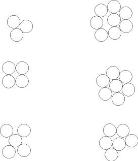
Is cross sectional area as much of a problem as how different numbers of conductors fit well together inside the connector?


I like how 3, 4, and 7 of same size fit together reasonably well, the others have some question on how good of a connection you can really make. This assuming all are same size, put mixed sizes together and could get more complicated to make them fit well

Did you draw these?
 
Is cross sectional area as much of a problem as how different numbers of conductors fit well together inside the connector?


I like how 3, 4, and 7 of same size fit together reasonably well, the others have some question on how good of a connection you can really make. This assuming all are same size, put mixed sizes together and could get more complicated to make them fit well
Three and four seem to work well, five - looks like could be tricky to keep them in even positions if you are twisting a spring connector onto them, seven is pretty even, but the center wouldn't have any contact with the spring just pressure against it from the surrounding six and could possibly be pulled out - leaving them all with weak contact after that happens.

Six and eight conductors just don't look like it makes all that reliable of a connection.


I have 8 #12 solids, they look great. Also the wire connector that I have used without pre-twisting.

Also I took a picture of the end of #3 copper. All those conductors are bound together just fine.

I think if in your drawing if you were to twist them together and cut the end of you will have a perfectly twisted conductors without major air void in between like your drawing shows.

UPDATE: the photos did not work properly. I had to remove the link. How do I post pictures??
 
Last edited:
I have 8 #12 solids, they look great. Also the wire connector that I have used without pre-twisting.

Also I took a picture of the end of #3 copper. All those conductors are bound together just fine.

I think if in your drawing if you were to twist them together and cut the end of you will have a perfectly twisted conductors without major air void in between like your drawing shows.

UPDATE: the photos did not work properly. I had to remove the link. How do I post pictures??
You can process them to a lower resolution and upload them to the Forum site or else link to a photo site that does not require a login and allows deep linking.

Sent from my XT1585 using Tapatalk
 
I have 8 #12 solids, they look great. Also the wire connector that I have used without pre-twisting.

Also I took a picture of the end of #3 copper. All those conductors are bound together just fine.

I think if in your drawing if you were to twist them together and cut the end of you will have a perfectly twisted conductors without major air void in between like your drawing shows.

UPDATE: the photos did not work properly. I had to remove the link. How do I post pictures??

Lets see if these work.
View attachment 17919 This is the end view of #3 in regards to Kwired drawing.
View attachment 17920 This is after I took off the blue wire nut. You will see a bit of conductor separation it is because when I took off the wire nut it somewhat twisted the conductors backwards.
View attachment 17921View attachment 17922
 
Combination of solid or stranded, when they are pre-twisted together the blue wire nuts work great. If they are all solids no pre twisting is required, the blue wire not does the twisting for you. Assuming you have removed proper insulation.

I'm aware of that, this is not my first rodeo. In any case, a large blue wirenut is not listed for that many conductors and is therefore not a reliable connection IMO.

What do you do when you have three #8s to connect together?

Whatever connector is listed for that combination, which off the top of my head would be a 3-port polaris/clear tap. Now, if it's 3:55 on a Friday, whatever is convenient. ;)
 
I'm aware of that, this is not my first rodeo. In any case, a large blue wirenut is not listed for that many conductors and is therefore not a reliable connection IMO.


Whatever connector is listed for that combination, which off the top of my head would be a 3-port polaris/clear tap. Now, if it's 3:55 on a Friday, whatever is convenient. ;)

Everybody does things their way and according to their experience.

Why the blue wire nut not listed for 8 #12 conductors?

Unless I did the math incorrectly, otherwise it shows that it is OK.
 
Everybody does things their way and according to their experience.

Why the blue wire nut not listed for 8 #12 conductors?

Unless I did the math incorrectly, otherwise it shows that it is OK.

Generally if I have to resort to a large blue wirenut for any type of splice I tend to question my professionalism.
Although I don't question my split bolt I brought up earlier which violates its listing.

Now isn't that odd ?

Probably because I know once a wirenut gets that big that it's nothing more than a pretty hat on whatever happens to be underneath it.

JAP>
I tend to agree with you.
 
Generally if I have to resort to a large blue wirenut for any type of splice I tend to question my professionalism.
Although I don't question my split bolt I brought up earlier which violates its listing.

Probably because I know once a wirenut gets that big that it's nothing more than a pretty hat on whatever happens to be underneath it.

JAP>

Now isn't that odd
?VERY odd. ;);)


Each person does things different based on experience and belief. For me I can not trust the WAGO push in connectors. unless I have to use them.
 
I have 8 #12 solids, they look great. Also the wire connector that I have used without pre-twisting.

Also I took a picture of the end of #3 copper. All those conductors are bound together just fine.

I think if in your drawing if you were to twist them together and cut the end of you will have a perfectly twisted conductors without major air void in between like your drawing shows.

UPDATE: the photos did not work properly. I had to remove the link. How do I post pictures??
Your # 3 copper is likely 19 strands not 8, though it could be 7 strand. They choose those numbers of strands based on how well they do lay together to compose an overall round outer shape.

If they are compact conductors the strands are not round but rather shaped to eliminate nearly all voids in between them. Compact conductor will have same cross sectional area of material, but less overall diameter because there is less voids.

Otherwise if you bundle round objects of same size together there will be voids between them unless you compress them to/beyond the point of distortion. That was the point I was trying to illustrate. If you can lay the conductors so that voids are all equal then equal pressure surrounding them holds them together well, if it is difficult to make them equal then it will be more difficult to wrap something around them and maintain equal pressure on all of them, let alone the effects when you are twisting the item you wrap around them. Pre twisting conductors - especially when there is more then three or four does help make a more reliable connection IMO as you are not depending entirely on the connector for making contact, but rather to assist in holding things in place.
 
Lets see if these work.
View attachment 17919 This is the end view of #3 in regards to Kwired drawing.
View attachment 17920 This is after I took off the blue wire nut. You will see a bit of conductor separation it is because when I took off the wire nut it somewhat twisted the conductors backwards.
View attachment 17921View attachment 17922

Great pictures. One issue I see is that the center conductor is not touching the spring connector in the wire nut. It also looks like it isn't twisted, rather the other conductors are twisted around the center conductor. I wonder if there is a difference in how much force it takes to loosen or pull out the center conductor vs. the outside conductors.
 
ut. You will see a bit of conductor separation it is because when I took off the wire nut it somewhat twisted the conductors backwards.
View attachment 17921View attachment 17922
How did you verify that?

Cutting the end off the connector while installed would better tell us how they fit together when installed.

I too have concerns of how well center conductor is connected. It may have fair pressure from outside conductors, but if able to be pulled out, now you left a void in the center and contact pressure of all of them is likely compromised.

Would that not be the case for any connection if you jerked one of the conductors out ? :)

JAP>
 
How did you verify that?

Cutting the end off the connector while installed would better tell us how they fit together when installed.

I too have concerns of how well center conductor is connected. It may have fair pressure from outside conductors, but if able to be pulled out, now you left a void in the center and contact pressure of all of them is likely compromised.

Because when I was taking the WN off the wires where twisting backwards. The WN in the picture does a great job holding the wires together. I see your concern with the center conductor. Later today I will undo the cnductors and see what they all look like, especially the center one.
 
Would that not be the case for any connection if you jerked one of the conductors out ? :)

JAP>
Not a multiport connector that individually secures each conductor - like a WAGO, Polaris connector, terminal strips, ground bar....
 
Status
Not open for further replies.
Top