Multi-service ATS -- What a mess!! Help!

Merry Christmas
Status
Not open for further replies.

ramdiesel3500

Senior Member
Location
Bloomington IN
Okay, here's my delima!
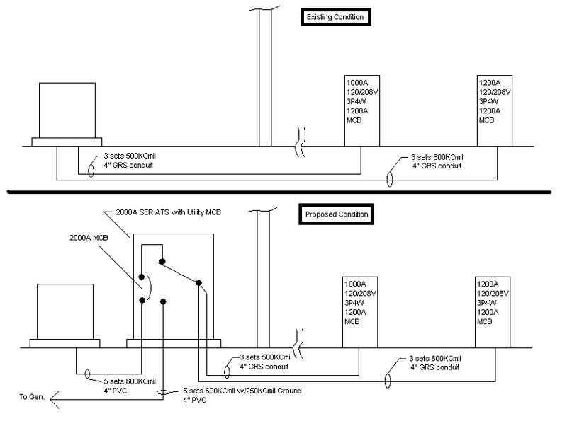
Got a building that has a POCO pad mount transformer out front in the yard. Building has two different service entrances, both inside the building far from the outer walls and both fed from that transformer out front. Service #1 is 1000A, 120/208V, 1000A MCB. Service #2 is 1200A, 120/208V, 1200A MCB. Feeders for both services are buried beneath the slab and, technically, enter the building directly into the bottom of each of the service cabinets. Owner now wants to install a generator to run the entire facility during a utility outage. (his cost of lost production is astronomical!!) It has been proposed that we install a 2000A 120/208V service entrance rated ATS beside the POCO transformer. ATS has a 2000A SER Main Breaker on utility line side. It has also been proposed that we tap the load side of the transfer switch to feed the two services. 240.21(B)(5) seems to support this approach, but my gut tells me we need to install OCP and/or disconnecting means for each feeder at the ATS. I suppose the existing main breakers at each service will protect their line side conductors just as before, but it just seems strange to me.

Your thoughts and comments will be greatly appreciated! Thank-you!
 
If you put the ATS at the transformer you have moved the buildings service disconnect and as you guessed that will require that the feeders leaving the ATS will now need OCP.

Unless you can sneak in under 250.32(B) you will also have to provide EGCs in those conduits that used to contain service conductors but will now contain feeders.

You would also have to separate the neutrals and grounds at the two old service disconnects.

You will have to check and see if that is even possible with the original service disconnects.

It will not be cheap but if the down time costs are astronomical it could be a gold mine of a job. ;)
 
Let me see if I get this:

As it currently stands, you have service entrance conductors, which are not protected at their ampacity at the supply end, but which are protected at the load end.

Once you install the ATS, these service entrance conductors become feeders. They would not be protected at their ampacity at the supply end, but would still be protected at the load end.

If the POCO owned the generator and the ATS, then these would still be service entrance conductors, and thus still legal.

Wouldn't this fall under 240.21(B)(5) Outside Taps of Unlimited Length?

-Jon
 
winnie said:
Wouldn't this fall under 240.21(B)(5) Outside Taps of Unlimited Length?

-Jon

The ATS as it will be the service disconnect will need OCP at it.

That being true I do not see the conductors leaving the ATS as Transformer taps.
 
Bob,
That being true I do not see the conductors leaving the ATS as Transformer taps.
240.21(B)(5) is for feeders, not transformer taps and looks like it would apply in this application. It is likely that an EGC would be required, but if the raceway is metallic that would serve the purpose and yes, the grounded and grounding conductors would have to be seperated at the two building disconnect switches.
Don
 
don_resqcapt19 said:
Bob,

240.21(B)(5) is for feeders, not transformer taps and looks like it would apply in this application.

Ahhh, OK :cool:

I was working from memory, no code book at this location. :)
 
I must be drawing an incorrect sketch of this proposed installation, for my sketch looks way, way wrong. You say that you would ?tap the load side of the transfer switch (singular) to feed the two services (plural).? That tells me that you are talking about one transfer switch. If you connect both sets of (what are now called) service conductors at the ATS, then you are placing the two services in parallel, even when they are served by the utility. I?m fairly sure that is not what you have in mind.

Can someone draw and post a sketch of, or simply describe in clear and simple words, the connections to the ATS from the two service transformers and the generator, and the connections from the ATS to the two main boards?
 
Bob, Jon, and Don
Thanks for your replies and discussion! I believe the feeders are in GRS Conduit which will help. In the event we find they are in plastic, we will pull them out and re-pull with and ECG. Separation of neutrals and grounds at the two services should not be difficult in this case. (pretty sure they were separated anyway and just bonded with a single piece of bonding hardware. will confirm.)
Thanks again!
 
Here is a diagram of the existing condition and the proposed solution.

ATSScenario.jpg
 
So, does anybody out there see a code violation with this arrangement? I, personally, have been unable to find a violation. When I first saw this, I thought a 2000A, MLO distribution panel would need to be installed at the load side of the transfer switch with one 1000A and one 1200A branch breaker. Now I am becomming convinced it is not necessary.
 
I think that you are good to go as long as the building disconnects are "nearest the point of entry".

Don
 
LarryFine said:
My thought, too. As long as one generator can run two ATS's, either directly or in a 'master/slave' setup.


Larry I do not understand, what is a master slave setup?

Generators do not control ATSs........ ATSs control generators.

Connect as many ATSs as you want.:smile:
 
Status
Not open for further replies.
Top