Need schematic

Status
Not open for further replies.

Smart $

Esteemed Member
Location
Ohio
K2500 said:
...Stops should be in series ahead of reset/starts, so that the PB must be reset before anything starts moving again...
Actually, the stops can be anywhere in series on the hot side of the coil... the main thing is, which you were correct to point out, is that the momentary switch parallels only the aux n.o. contact. I missed that because I got stuck in "drawing mode only, and forgot about circuit evaluation.

Which takes us to where the momentary/aux switching portion of the control circuit could be put ahead of the PB's such that there are no hots going to either PB in "shutdown mode".
 

Smart $

Esteemed Member
Location
Ohio
nakulak said:
that's if they are wired NC, I thought he was wiring them NO, (you are correct, they should be NC, )
I don't even know how to wire a stop N.O. without bringing some other control device into the picture.:grin:

Even with other devices in the picture, I'd never wire a stop N.O. if it's up to me. I believe a stop should always be wired in fail-safe manner, i.e. a short or fault in the circuit will also function the same as a manual stop.
 

Smart $

Esteemed Member
Location
Ohio
e57 said:
Smart$,
...what are you doing this schematic with?
I drew it up in a program called Canvas, which is now owned and marketed by ACD, same one that puts out ACDSee. It is not a schematics program. I could use other programs to draw up schematics, but Canvas just happens to be the only graphics-type program I have installed on this computer as I only recently assembled it.
 

K2500

Senior Member
Location
Texas
Smart $ said:
Which takes us to where the momentary/aux switching portion of the control circuit could be put ahead of the PB's such that there are no hots going to either PB in "shutdown mode".

Though I never thought about, it sounds like good practice to de-energize the stop station. In series ahead of coil might make the status indication(plc alarm ect.) simpler, but thats a whole 'nouther animal.
 

Smart $

Esteemed Member
Location
Ohio
K2500 said:
Though I never thought about, it sounds like good practice to de-energize the stop station. In series ahead of coil might make the status indication(plc alarm ect.) simpler, but thats a whole 'nouther animal.
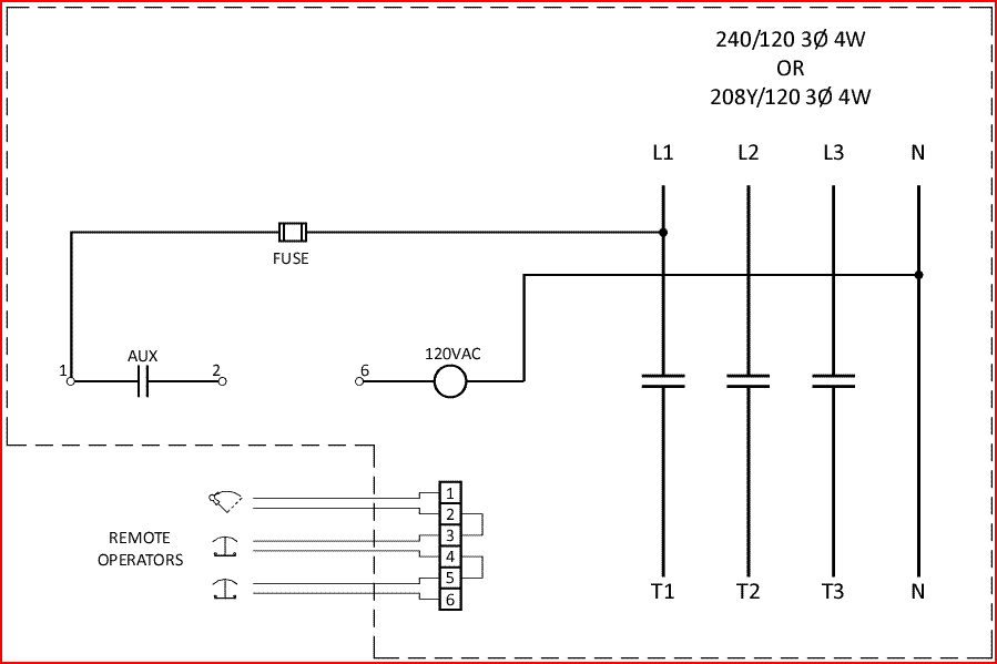
Revised schematic...

Capture3.gif
 

Smart $

Esteemed Member
Location
Ohio
brother said:
good drawing, just out of curiousity where would they place the 2 e stops in the shop?? by the teachers desk, the entrance?
More information is required to make that determination.
 

rkrieger

Member
Project is completed

Project is completed

I'm still having "issues" with posting my schematic, but some of you have asked where the E-stops and key switch was located. NATEF states in their standards, "centrally located". so, we put one stop on a hoist column in middle of shop, then other and key re-set just outside of tool crib which also is in a "central location". Everything functions as it should. Thanks again for all the posts, drawings and comments.

RLK
 

e57

Senior Member
rkrieger said:
~but some of you have asked where the E-stops and key switch was located. NATEF states in their standards, "centrally located". so, we put one stop on a hoist column in middle of shop, then other and key re-set just outside of tool crib which also is in a "central location".
I'm sure some of us were thinking of location in the circuit - not where physically....

Anyway - to deal with attachement - the next time you post, there is a box below where you are typing called 'Additional options' see the area marked:
Attach Files
Valid file extensions: bmp doc gif jpe jpeg jpg pdf png psd txt

(Click the box below it - hit 'browse' for your file - located and click the file you want to upload, then hit "Upload"
 

rkrieger

Member
Verbal Circuit Schematic

Verbal Circuit Schematic

OK, now that I know what the "where in the circuit" means....here is a "verbal description" of our circuit. I know about the "attach files" icon, but being a PC novice, I am having difficulties using URL's to attach the file. Larry Fine, (bless his heart), did some of the preliminary work to help me, but even after that, I am still having "issues"

CIRCUIT EXPLANATION = Being a single phase system, we took a tap from one of the line sides of the contactor, fed an in-line fuse, then to the two E-stop mushrooms (in series), then to one side of the N.O. Momentary Key Switch. Also, from the same terminal of the Key Switch, ran back to one side of a set of N.O. contacts controlled by the contactor. From the other side of the Key Switch, ran to the other side of the N.O. contacts and also from that terminal to the + side of the contactor coil. Obviously, the other side of the contactor coil is neutral.

Hope the above words explains what we did until I can get my act together on the pic's.

Thanks,
RLK
 

HighWirey

Senior Member
"I had hoped the schematic would be displayed, not just attached. Still better than a poke in the eye with a sharp stick"

ptonsparky,

Your schematic is correct, and very clear. Nice work.

Merry Christmas Everyone and Best Wishes
 

cschmid

Senior Member
stickelec said:
RK, I can tell from your first two posts that you are eager to be an active participant in the design meeting of which you speak. "I have been there myself", and with that in mind I offer the following:

I feel there are just too many unknowns to offer "a wiring diagram", plus I would think emergency-systems design in the public domain carries with it quite a responsibility.

I would rather respectfully submit for your consideration a different approach to your participation. As you know, long before a project moves to the "wiring diagram" phase, a lot of design work has to take place. Perhaps you could step-in as a design coordinator, you might be surprised at how favorably that would be received among your peers. Once the scope is clearly defined and documented, you could then move to the next phase.

If you then want to take a shot at designing the logic, I would encourage you to Google "Relay Ladder Logic" (or similar) and make it happen on paper. You would then, of course, want to work through the review process with other qualified professionals. Because it could be considered life-safety, I would encourage you to seek the assistance of a qualified professional well versed in the various code requirements.

If you want to pursue the development of a project scope, I would be glad to offer a list of things that might be of value.

This is a very good comment you need to take into advice..I have already notice that you have other energy source you need to consider before you de-energize the main panel..I also want to know if a shunt trip can and will fail safely every time..I don't think it meets the requirment..You definitely need a safety audit so you can create a system that is effective for years to come..remember someones child's health and welfare is at stake..


Can you guys tell me the various programs you use for schematics and how you like them??are they easy to use and inexpensive..
 
Last edited:

rkrieger

Member
Thanks Larry

Thanks Larry

:smile: In spite of your help, I still had issues posting the URL's. :-? Don't know why, but thanks for your "intervention". The shop had the initial NATEF inspection yesterday and they indicated the power disconnect system was totally compliant with their spec's. We are also applying for a MIOHSA safety audit to be double sure.

Thanks again.

RLK
 
Status
Not open for further replies.
Top