Negative power factor and PV systems

Status
Not open for further replies.
"Negative" power factor

"Negative" power factor

I am an instructor of basic circuit theory in a community college in the Southwest USA. I hope none of my students will see the discussion about "negative" power factor. The power factor in AC circuits has always been defined as the cosine of theta; and alternatively, as the ratio of real power (watts) divided by apparent power (VA), or in basic circuit solutions, the circuit resistance divided by the circuit impedance. Power factors can be lagging (the usual case) or leading. Numerically the power factor is always a postive number between 0.0 and 1.0 (never a negative number). These concepts can be clearly shown by drawing a graph of the voltage and current sine waves. The power factor angle (theta) represents a time delay that occurs in AC circuits between the voltage sine wave and the curent sine wave. The graph is usually drawn with time zero at the left hand edge and one complete sine wave shown ending at time 16.8 milliseconds at the right hand edge. This time interval represents an angle from zero degrees to 360 degrees. Please note there are no "negative" angles here and no "negative" values of the cosine. The power triangle of any AC system or circuit consists of watts, inductive reactance Vars and capacitive reactance Vars. Regardless of the quantity of these three components, the resulting power factor is either leading or lagging, but never a negative number. If a PV system produces a leading power factor the related utility should be very happy because the PV system will produce a higher power factor for the entire system. It would be like the utility installing a capacitor bank in the system to improve system power factor, except it would be for free. I've been teaching for 13 years and have never seenb a textbooik that referred to a "negative" power factor and I hope it does not become common usage.
 

mivey

Senior Member
110603-2237 EDT

mivey:

I agree with you that negative power factor is sort of goofy, but I was trying to come up with some definition that might explain what tallgirl had in mind. It appears that this definition is what she had in mind.
I agree with that and said pretty much the same in a prior post.
I do not know what useful purpose this usage has. As I said in my comment to tallgirl I am more interested (negative) power than a negative power factor as a measurement tool.
I was using the term "you" in general and did not think you in particular would be using such a term. I understand what you were saying and agree with what you posted. Sorry I was not clear about that.

Some meters use arrows as indicators instead of a negative sign. Power meters store the accumulations in separate registers (i.e., delivered and received registers) and there is no negative to speak of.

Maybe what a power company might want to have is both a VARH meter and a KWH, and that with new meters this also should mean the power company could get short time average power and VAR..
We do exactly that on demand customers. However, all of the rates I have seen use a peak var and peak kW as a penalty calculator. That is not to say the customer will get away with a heavy var load as a proper demand rate is designed to charge for a poor load factor as well. With a solar panel, the customer will eventually set a normal kW peak and then the load factor penalty would hit.

If you suspect the kW will never have a normal peak (i.e., the solar panel will always be running during peak load), there is the option to use a peak kVA demand or even use the kWh and kvarh to calculate an average kVA.

Yes, that means eventually the small commercial and residential customers will be on demand rates (some already are). The age of DG as well as other things like electric instant hot water heaters makes this inevitable.
 

tallgirl

Senior Member
Location
Great White North
Occupation
Controls Systems firmware engineer
These concepts can be clearly shown by drawing a graph of the voltage and current sine waves. The power factor angle (theta) represents a time delay that occurs in AC circuits between the voltage sine wave and the curent sine wave.

That's only the case if current is an unsigned quantity. If current has a directional (sign) component, cos(theta) very much can be negative. cos(Θ) is positive from -Π/2 (3Π/2 -- there are 4Π/2 radians in a cycle) to Π/2, and negative from Π/2 to 3Π/2.

You can't say the voltage is negative -- it's very obviously positive when it's positive. Nor can you say that when a PV system is 'exporting' power than the power is positive. That kinda leaves you with current being negative, and that leaves you with negative power factor.

If a PV system is making unity power factor power, the phase angle (Θ) between the maximum voltage and the maximum current is Π, cos(Π) = -1.
 

Besoeker

Senior Member
Location
UK
If a PV system is making unity power factor power, the phase angle (Θ) between the maximum voltage and the maximum current is Π, cos(Π) = -1.
That's an odd concept, with respect.

Suppose the output from the PV system goes through a transformer to match voltages. For simplicity, let's say it's a single phase transformer and that it feeds a pure resistive load, so unity power factor. The current and voltage would be in phase, not anti-phase.

In reality, if the inverter is producing output power at unity power factor, it doesn't matter if it is going into a passive resistor or into the utility supply.
 

mivey

Senior Member
That's only the case if current is an unsigned quantity. If current has a directional (sign) component, cos(theta) very much can be negative. cos(Θ) is positive from -Π/2 (3Π/2 -- there are 4Π/2 radians in a cycle) to Π/2, and negative from Π/2 to 3Π/2.
But by definition current will only lag or lead by 90? so throw that thought out.

You can talk about phase shifting by more than 90 degrees, but that is a different subject.

You can't say the voltage is negative -- it's very obviously positive when it's positive.
Why not? It depends on your reference.

Nor can you say that when a PV system is 'exporting' power than the power is positive.
Sure you can. That is the traditional and normal way to look at it.
That kinda leaves you with current being negative, and that leaves you with negative power factor.
Nope. You are getting your wires crossed.
If a PV system is making unity power factor power, the phase angle (Θ) between the maximum voltage and the maximum current is Π, cos(Π) = -1.
Hardly. The "-" symbol is just a placeholder to tell you the direction of power flow. It is not an indicator of a negative power factor.

No more so than looking on my meter that shows "<" for power delivered to the utility and ">" for power delivered to the retail customer. I would never call it "<1" or "less than unity" or ">1" or "greater than unity" because it is just a symbol that represents something else.
 

K8MHZ

Senior Member
Location
Michigan. It's a beautiful peninsula, I've looked
Occupation
Electrician
So, just what was this 'REMF' I was taught about?

The concept of power going in either direction was explained nicely in my old text books. Never once was REMF assigned a 'negative power' value.

One thing I have learned is that there are people that use the term 'negative power' when they mean REMF. At least now I know what they are trying to say.
 

gar

Senior Member
Location
Ann Arbor, Michigan
Occupation
EE
110605-1157 EDT

K8MHZ:

Please define what "REMF" is. I did not find a useful answer doing a quick look on the Internet.

If we consider a resistive load, then power is usually considered as a scalar quantity, but it seems useful to assign it a + or - value. This is advantageous when viewing a point in a system and writing an equation for the power to or from a source.

Consider a battery. This is a device wherein current or energy can flow out of the device or into it. If we choose sign conventions so that current out of the battery is + and the voltage is + when this occurs, then power out, P = V * I, is positive. When current flows in the sign changes and so does the sign of the calculated power.

So negative power from a battery is an indication of power into the battery.

.
 

K8MHZ

Senior Member
Location
Michigan. It's a beautiful peninsula, I've looked
Occupation
Electrician
110605-1157 EDT

K8MHZ:

Please define what "REMF" is. I did not find a useful answer doing a quick look on the Internet.

If we consider a resistive load, then power is usually considered as a scalar quantity, but it seems useful to assign it a + or - value. This is advantageous when viewing a point in a system and writing an equation for the power to or from a source.

Consider a battery. This is a device wherein current or energy can flow out of the device or into it. If we choose sign conventions so that current out of the battery is + and the voltage is + when this occurs, then power out, P = V * I, is positive. When current flows in the sign changes and so does the sign of the calculated power.

So negative power from a battery is an indication of power into the battery.

.

Gar,

As I was taught (in a motor controls class), REMF is 'Reverse Electromagnetic Force'. I have also seen it referred to as 'Counter EMF' or 'Back EMF'.

In an electric motor, the rotor acts like a generator once it starts spinning. The rotor actually pushes EMF back toward the supply. The resultant current draw is actually the in rush current less the REMF. That is why when you slow a rotor down (increasing slip) the current will rise. The current in the field coils is not being counter acted as much by the rotor's REMF and of course the field coils will suffer excess I^R heating.

So, to me, a grid tied power supply is acting just like the rotor in a motor, feeding EMF back to the primary supply.

In our calcs we assigned values to both the flow into the motor and the flow back out. They were both positive values. One was 'forward' and one was 'reverse'. Never did we discuss such a thing as a 'negative power factor'.

We were taught that power factor was a relationship between Watts and Vars and had nothing to do whatsoever with which way through the conductor it was traveling.

I couldn't find anything on the 'net about REMF in motors, but found a bit on transformers.


I believe that you are referring to "back EMF" that is generated in a coil or transformer.

When you put an AC voltage across the primary of a transformer, that generates an AC (lagging) current in the primary. That AC current generates an AC magnetic flux, which couples to the secondary coil. That changing flux induces a current in the secondary coil, which generates its own flux in the core, and that secondary flux opposes the primary flux. So any current flowing in the secondary causes a reduction of input impedance in the primary (the so-called Back EMF, or reverse voltage due to the reflected load impedance).

Does that help?

http://www.physicsforums.com/showthread.php?t=173714
 

K8MHZ

Senior Member
Location
Michigan. It's a beautiful peninsula, I've looked
Occupation
Electrician
I would also like to add that even though it appears I am talking about current, we actually took measurements inside electric motors. In a 120 volt motor, we saw resultant voltages of around 5 volts, meaning the REMF was 115 volts for that particular motor.

It's been a while since that class, and it was only one day that we spent on the motors themselves so I am not clear on the particulars, like where the measurements were taken from, what type of motor, etc. Also, this is the first time since my motor controls class I have even thought about it. It's just that when this topic came up, it rang a bell and reminded me of what is supposedly happening inside electric motors.
 

mivey

Senior Member
I couldn't find anything on the 'net about REMF in motors, but found a bit on transformers.
I believe that you are referring to "back EMF" that is generated in a coil or transformer.

When you put an AC voltage across the primary of a transformer, that generates an AC (lagging) current in the primary. That AC current generates an AC magnetic flux, which couples to the secondary coil. That changing flux induces a current in the secondary coil, which generates its own flux in the core, and that secondary flux opposes the primary flux. So any current flowing in the secondary causes a reduction of input impedance in the primary (the so-called Back EMF, or reverse voltage due to the reflected load impedance).

Does that help?

http://www.physicsforums.com/showthread.php?t=173714

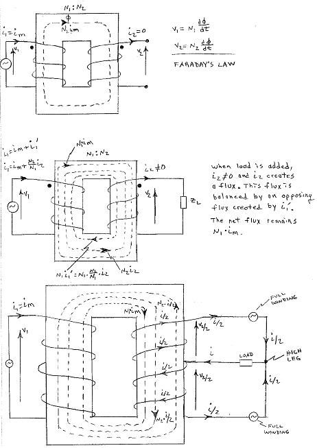
There is a little more going on than that. There are two components. One is the flux that creates the secondary voltage (Faraday's Law). The other is the opposing flux that will keep the net flux the same as when you have an open secondary.

See the first two pictures here (ignore the 3rd picture as that was dealing with a response I made concerning a load connected to a delta high-leg):
HighLegFlux.jpg
 

tallgirl

Senior Member
Location
Great White North
Occupation
Controls Systems firmware engineer
You can talk about phase shifting by more than 90 degrees, but that is a different subject.

No, it isn't a different subject at all. You presented a cosine(Θ) based definition of "power factor" and I just applied it is all. You're completely stuck in an out-dated "power only goes one way" universe and instead of just admitting you're wrong, you're now claiming that some "definition" prevents the voltage and current phase relationship from exceeding +/- Π/2 radians. Well, times change. Relative to a reference frame in which voltage and current are positive, it is now possible for voltage to be positive and current to be negative.

Why not? It depends on your reference.

Do words and measurements =actually= mean anything? In particular, for a 120 VAC system, the voltage is a measurement of the root mean square voltage of the conductor. The only reason RMS voltages are always positive is because of what "root mean square" means and the convention that the positive root is the one that is used (square roots have two solutions -- one positive, the other negative ...).

Changing an AC voltage by =any= DC offset increases the RMS voltage by the magnitude of the DC voltage the AC voltage rides on). Which pretty much means it's impossible to ever have a negative RMS voltage, even if you try playing games with the AC, unless you through more than a hundred years of what "Volts, RMS" means out the window.

Sure you can. That is the traditional and normal way to look at it.

On which planet?

No, seriously -- on which planet is "power" an absolute value with no direction, because the =definition= of "power" is either "volts * amps", or it isn't. You can't make "volts" arbitrarily negative without breaking everyone else and arbitrarily deciding which way volts is volts based on which way current is heading -- and the physics of "current" makes it very obvious that current has a direction (sign).

Nope. You are getting your wires crossed.

No, I'm not. The direction of current flow determines the nature of the magnetic field created by a conductor on which said current is flowing. A change in current creates a magnetic field that is directly related (in a counter-clockwise manner ...) to the direction of current flow. You want to have current be an absolute value measurement, in which case AC transformers no longer work. Since the Laws of Nature aren't subject to whim, I think they're going to ignore your request to cease working properly.

Hardly. The "-" symbol is just a placeholder to tell you the direction of power flow. It is not an indicator of a negative power factor.

I used your definition for "power factor" -- cosine(Θ), where Θ is the phase angle different between the same location on the voltage and current waves. Don't complain to me when it produces a negative value for Θ between Π/2 and 3Π/2 radians.

No more so than looking on my meter that shows "<" for power delivered to the utility and ">" for power delivered to the retail customer. I would never call it "<1" or "less than unity" or ">1" or "greater than unity" because it is just a symbol that represents something else.

Your meter isn't the basis for Physics or Electromagnetics. Fortunately.
 

mivey

Senior Member
No, it isn't a different subject at all.
Yes, it is a different subject all together.

You presented a cosine(Θ) based definition of "power factor" and I just applied it is all.
But you failed to follow what the formula was meant to tell you.

You're completely stuck in an out-dated "power only goes one way" universe...
I did not say "power goes only one way". I fact, I have said the opposite. And since when was "power goes one way" dated? Power has been known to flow in different directions for about as long as power has been discussed in human history.

...and instead of just admitting you're wrong, you're now claiming that some "definition" prevents the voltage and current phase relationship from exceeding +/- Π/2 radians.
Given a generator instead of a load with a normal impedance, the voltage and current can indeed lag or lead each other more than 90 deg. But you fail to get what we have defined. We have defined the magnitude of the active component relative to the magnitude of the apparent component.

The phase angle of the voltage is one of the components that is used to calculate the power factor of a normal load. Instead of getting caught up in some new definition have you stopped to consider the goal of the calculation? You are missing the intent of using the angle between the voltage and current. We are really after the percentage of apparent (total) power that is composed of active (real) power. This factor shows the relationship between the real component of power that our equipment has to handle and the total power that our equipment has to handle.

In other words, the angle we are after is the angle between the current on the real axis and the total current. For normal loads, the active power is in phase with the voltage because it is a resistive component of the load. But for any load you want, call it positive or negative real or positive or negative reactive, we get two components: one on the real axis and one on the imaginary axis. These components add vectorially to give us the total component. Indeed, you will often find the definition of power factor as pf = |I_real|/|I_total|.

The angle between the active and apparent power (or current) will be between zero and 90. On planet Earth, that is the nature of a rectangular coordinate system. It should be no mystery why cosine was used to map the real component.

I will concede that using lag or lead is probably not the best choice when discussing the relationship between the active and apparent current.

Well, times change. Relative to a reference frame in which voltage and current are positive, it is now possible for voltage to be positive and current to be negative.
Time has nothing to do with it. In case you did not know, it has always been that way.

Do words and measurements =actually= mean anything? In particular, for a 120 VAC system, the voltage is a measurement of the root mean square voltage of the conductor. The only reason RMS voltages are always positive is because of what "root mean square" means and the convention that the positive root is the one that is used (square roots have two solutions -- one positive, the other negative ...).

Changing an AC voltage by =any= DC offset increases the RMS voltage by the magnitude of the DC voltage the AC voltage rides on). Which pretty much means it's impossible to ever have a negative RMS voltage, even if you try playing games with the AC, unless you through more than a hundred years of what "Volts, RMS" means out the window.
Give me any voltage you want and I will give you a reference frame in which that voltage is a negative. You do realize that we have RMS current don't you?

On which planet?

No, seriously -- on which planet is "power" an absolute value with no direction, because the =definition= of "power" is either "volts * amps", or it isn't.
On planet Earth, we have some machines that are generators and some machines that are motors. The traditional method sees a generator as having a positive power output, not a negative output. But you can view it either way with no real harm done. Knock yourself out.

For you to say
tallgirl said:
Nor can you say that when a PV system is 'exporting' power then the power is positive
is really quite silly. Not only are you wrong, you are arguing against your own self because you are now saying the direction must be fixed the other way.

You can't make "volts" arbitrarily negative without breaking everyone else and arbitrarily deciding which way volts is volts based on which way current is heading -- and the physics of "current" makes it very obvious that current has a direction (sign).
The choice of direction is completely arbitrary. I can base it on a reference voltage or a reference current. Also, in case you were not aware, voltage is bound by physics just like current is bound by physics because it is a physical phenomena, not just some mathematical construct.

No, I'm not.
Yes, you are.

The direction of current flow determines the nature of the magnetic field created by a conductor on which said current is flowing. A change in current creates a magnetic field that is directly related (in a counter-clockwise manner ...) to the direction of current flow. You want to have current be an absolute value measurement, in which case AC transformers no longer work. Since the Laws of Nature aren't subject to whim, I think they're going to ignore your request to cease working properly.
Complete twaddle.

I used your definition for "power factor" -- cosine(Θ), where Θ is the phase angle different between the same location on the voltage and current waves. Don't complain to me when it produces a negative value for Θ between Π/2 and 3Π/2 radians.
Then quit blindly applying a formula and try to figure out what the formula is supposed to do.

Your meter isn't the basis for Physics or Electromagnetics. Fortunately.
Fortunately, no meter is the basis for Physics or Electromagnetics. Fortunately for me, my meter does follow the laws of Physics and Electromagnetics.

Now you can define anything you want to in your world and no one will be able to argue since you are making the rules. But just because you make something up does not mean the rest of the world will follow your lead.

You are trying to take a negative sign that is a placeholder for the term delivered or received and turn it into something else. May I recommend you read the following:
Understanding Power Flow and Naming Conventions
 

tallgirl

Senior Member
Location
Great White North
Occupation
Controls Systems firmware engineer
But you failed to follow what the formula was meant to tell you.

In the DRG world, it really does mean something completely different. The sign really does matter. I'm sorry this is so hard for you to grasp, but I haven't the time to waste any further explaining it to you. For a free clue -- figure out the money aspect. What's the financial difference between importing 1KW at 90% power factor and exporting 1KW at 90% power factor.

You are trying to take a negative sign that is a placeholder for the term delivered or received and turn it into something else. May I recommend you read the following:
Understanding Power Flow and Naming Conventions

A placeholder for "delivered" and "received"? Is "volts" now a placeholder for "how much you get shocked"?

As an added bonus, I'm going to point out that you're now using "final power factor", not the one based on cos(Θ), which is a completely different animal.

For anyone who isn't bored, please tell them the phase angle relationship between current and voltage for a system having a final power factor of 90%. Feel free to pick "leading" or "lagging", as the mood may strike you.
 

DetroitEE

Senior Member
Location
Detroit, MI
For anyone who isn't bored, please tell them the phase angle relationship between current and voltage for a system having a final power factor of 90%. Feel free to pick "leading" or "lagging", as the mood may strike you.

Inverse cosine of .9 is 25.8 degrees. I'm not sure what you're getting at though...can you please elaborate on what this answer is supposed to reveal?
 

tallgirl

Senior Member
Location
Great White North
Occupation
Controls Systems firmware engineer
Why is it when people struggle to explain their point it tends to become personnel and then name calling and insinuations ensue?

Frustration?

The problems with PV/DRG power factor are unlike those in other situations because the impact to the grid is completely different, the money is different, voltage drop / gradients work differently, etc.

Yes, of course "power factor" has meanings that are well-established for many decades. And now people have to adjust to different meanings because things are different.

Something like negative RMS current, which is numerically impossible, has to be considered because otherwise we wind up with "received" and "delivered" which somehow behaves exactly like "+" and "-". If I stick with a traditional definition of RMS current, I can't calculate bus bar currents because I can't put a minus sign in front of "delivered" current. And I can't even calculate KWh consumption because "power" is stuck being positive. Or "received" and "delivered", which again happens to behave just like "+" and "-". So when someone says a sign that happens to act just like a sign is a "placeholder", I'm not convinced they are paying enough attention to respond intelligently. Which is very disrespectful.

You want a real example? Right now, this minute, L1 Irms at the PV interconnect is 2.4 amps, L2 is 3.4 and Irms at the A/C breaker is 16.2 amps. What's Irms at the lugs from the service?

I don't need to read some non-technical paper written by someone at Landis+Gyr. I've spent the last several weeks with my face buried in manuals from other vendors -- http://www.electroind.com/pdf/100s-manual.pdf, http://www.ccontrolsys.com/ww/images/2/28/WNC-MODBUS-Manual-V16.pdf, and if I can find a similar manual for the Landis+Gyr meters Oncor has been installing all over Texas, I'll bury my face in that. More than manuals and talk about "placeholders", I need numbers that work and make sense. Negative RMS current, as dumb and wrong as it may seem, works.
 
Last edited:

tallgirl

Senior Member
Location
Great White North
Occupation
Controls Systems firmware engineer
Inverse cosine of .9 is 25.8 degrees. I'm not sure what you're getting at though...can you please elaborate on what this answer is supposed to reveal?

Not for a final power factor value it isn't. It could be a switch-mode power supply that conducts during 90% of the cycle with no phase angle change in the current wave form.
 

kingpb

Senior Member
Location
SE USA as far as you can go
Occupation
Engineer, Registered
I am going out on a limb here and say I don't think anyone is trying to insult anyone else's inteligence. I believe statements have possibly been misinterpreted, which frankly, is exactly why I tell my kid's to quit texting and talk in person. It is often easy to misunderstand what someone writes. With that said, I will offer, simply as food for thought:

AC is AC, it has a negative and positive value as it goes through the cycle. The RMS value is going to be positive. We typically, and arbitrarily I might add, assign a + sign to the direction we think power will flow in the positive half of the cycle, knowing it actually changes direction in the negative half.

Also, power factor is defined as the cos(Vang - Iang). Current can lag voltage and current can lead voltage.

Mathematically, V assigned an angle of 0 deg, and current assigned an angle of 180 deg, does give you a value of cos (0 - 180) = -1, however, how will you make this happen? The difference between V and I are based on R, L, and C components in the circuit. A purely capacitice or purely inductive circuit is 90degrees. Therefore, the difference in angle cannot vary by more than +/- 90 degrees (full inductive or full capacitive). Any resistance added reduces the angle to something less than +/-90 degrees. The cosine in this case is always positive.

The CT or current clamp being used, if hooked up with the wrong reference will indicate negative values, including power factor. This would be an easier explanation than trying to deduce or explain that the laws of physics have changed. Have they? I will have to leave that question to much, much, much smarter people than myself. But, I certainly am not going to accept that they have based on a very vague two paragraph write-up by a PLC board snake oil salesman. To do so would mean I have to say my engineering degree from a top rated university is now toilet paper. How do I say, not going to happen............

I will close with, the sign (direction in power flow) is very important as it represents the relation between P, Q (watts & vars) and bus voltage in a system. Too much information to include here as it is presented uuslally as higher level power engineering material coverd over weeks of time. I will suffice to say that it can get tricky interpreting the minus sign as you are dealing with phasors that have magnitude and direction, complex conjugates, power in, power out, current in relation to voltage, and power factor.

Cheers~
 
Status
Not open for further replies.
Top