tallgirl
Senior Member
- Location
- Glendale, WI
- Occupation
- Controls Systems firmware engineer
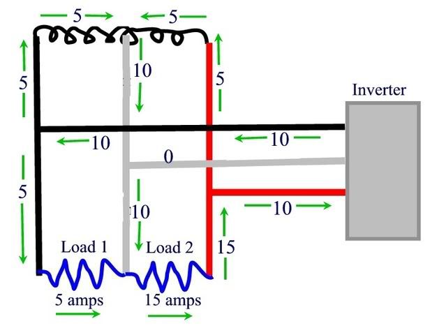
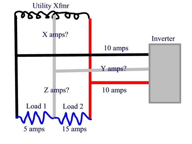
Apropos of nothing, on a 120/240 single phase system with one AC inverter on each leg, if one leg has a -5A "sell" current (the inverter is producing 5A more than being consumed) and the other leg has a 5A "buy" current (the loads on that leg are 5A more than the inverter is producing), the neutral current is 10A, right?
")