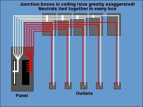
Neutrals, connecting all branch circuits neutrals together

Status
Not open for further replies.

RayS

Senior Member
Location
Cincinnati
realolman said:
I think maybe he's talking about more than one circuit.

2 multi wire circuits run in the same conduit would have two neutrals.
I don't think those two should be tied together. I think they should be identified some how to keep them with their respective circuits.

I agree. If you don't keep the neutrals separate, and you have to work on one of the circuits, you would have to deenergize all of the circuits so you would not be interrupting a live circuit. (even tho it's a neutral, when you break it, you have full line voltage)

Only time I ever tied multi circuit neutrals together was when we couldn't identify which went where, so we tied 'em all together so no individual neutral would be overloaded. I didn't like it, but it's what my boss said to do.
 

OldYeller

Member
Location
Nebraska
Thanks for all of the input. I will give a better description of the issue. There are 5 circuits in this run. They originate at a panel that is powered directly from a transformer. The ground and neutral are landed together at the panel as they should be as they are the first equipment after transformer. In the same conduit, there are 5 ungrounded conductors and 5 grounded conductors as well as 1 ground wire, this feeds 5 circuits. It is run in EMT and has mutiple general use outlets and well as lighting. At the first 4-square all of the grounded conductors as well as a wire for the first circuit are tied together. As the circuit runs end one by one as they are fed to there device or application, 1 ungrounded and 1 grounded conductor do not continue in the run since they are at there destination, but still in each box, all grounded conductors are tied together with a wire to that paticular device. In every box (jct point, 4-square), all wires are spliced-1 hot in spliced with same hot leaving, but all neutrals coming in and leaving are spliced together. The grounding conductor coming in and leaving to next box or device is spliced and has a drop, but it is only landed at the device, not landed in the box and then tied to the incoming and out going wires and the device.

Bottom line this whole run is a mess. I appreciate all of the help. And have got some great input. My problem with this run is that it is not to code as I read it and wasn't finding all that I needed to present to my boss to make this guy change how he wires. I need documantation from NEC to make the change. I just want all my ducks in a row before I present this to him.

I am a Maint. electrician and have only been in this position for just over a year. I have taken and am still taking classes at a Tech. school. I am very proud to be doing what I am doing and wish only to learn more and grow in this field. I hope that I was right in thinking tht I am in the correct forum. I appreciate any help.

Thanks, Allen

Sorry if this was to long.
 

Bob NH

Senior Member
How does the circumstance that is described differ from having a neutral run to a subpanel, with several branch circuits run from the subpanel, each with its own neutral.

If you draw the diagram, the neutrals look exactly the same, with the subpanel corresponding to the 4-square where the neutrals are connected. When you turn off one breaker, all of the neutrals are still connected at the subpanel.

NEC 240.20(B)(1) explicitly permits individual circuit breakers on the ungrounded conductors of multiwire branch circuits, so they appear not to be concerned about the possibility of power on one ungrounded conductor while the other is disconnected.
 

iwire

Moderator
Staff member
Location
Massachusetts
Bob NH said:
How does the circumstance that is described differ from having a neutral run to a subpanel,.

Bob I may be mistaken but I believe the issue is more than one MWBC.

You have neutral for 1,3,5 joined with the neutral for 7,9,11 etc.

In this case there will be parallel conductors from the point they meet back to the panel.
 

realolman

Senior Member
Latin language lesson:
Catapultam habeo. Nisi pecuniam omnem mihi dabis, ad caput tuum saxum immane mittam.
I have a catapult. Give me all your money, or I will fling an enormous rock at your head.

All right, gasbaggus maxima...:)

Does this mean anything?

Non illigitimus carborundum.

(I'm not sure if that's exactly right.)
 

infinity

Moderator
Staff member
Location
New Jersey
Occupation
Journeyman Electrician
At the first 4-square all of the grounded conductors as well as a wire for the first circuit are tied together.


Yes this is a problem since you now have 5 parallel grounded conductors coming from the panel. Also do you have one of these,

15042-L.jpg


to get all of that wire in the box? A 1900 box is definitely too small for this application.
 

Bob NH

Senior Member
iwire said:
Bob I may be mistaken but I believe the issue is more than one MWBC.

You have neutral for 1,3,5 joined with the neutral for 7,9,11 etc.

In this case there will be parallel conductors from the point they meet back to the panel.
I was using the NEC 240.20(B)(1) reference to show that the code explicitly permits a condition where one neutral is permitted to serve two or more ungrounded conductors which may be independently disconnected.

That is not different from a safety point of view than the circumstance described by the OP.

Also, 215.4 permits multiple feeders with a common neutral, which is a similar schematic situation.

Connecting the neutrals in a box produces the same electrical schematic for the neutrals as would result from having a subpanel at the same point. If you had a 100 amp subpanel with an 80 amp circuit and a 20 amp circuit, then the voltage drop in the neutral from the 80 amp load back to the service point would produce the same potential on the neutral of the 20 amp circuit. That it no different than the result for the system described with the neutrals tied together.
 

iwire

Moderator
Staff member
Location
Massachusetts
Bob NH said:
Connecting the neutrals in a box produces the same electrical schematic for the neutrals as would result from having a subpanel at the same point. If you had a 100 amp subpanel with an 80 amp circuit and a 20 amp circuit, then the voltage drop in the neutral from the 80 amp load back to the service point would produce the same potential on the neutral of the 20 amp circuit. That it no different than the result for the system described with the neutrals tied together.

Bob we definitely are having a misunderstanding here, and it may be entirely on my end.

I don't think you and I have the same circuit in mind.

The circuit I have in my mind has parallel neutrals.

To apply it two your sub panel example the sub panels feeder neutral would not be a single conductor but a collection of small conductors run between the sub and main panels.
 

George Stolz

Moderator
Staff member
Location
Windsor, CO NEC: 2017
Occupation
Service Manager
OldYeller said:
In the same conduit, there are 5 ungrounded conductors and 5 grounded conductors as well as 1 ground wire, this feeds 5 circuits.
Here is how I view the installation Allen is describing, and I think Iwire is viewing it the same way:
Neutralstiedtogether.jpg

This is a 310.4 violation. As Iwire has mentioned, there should not be any EMF issues, as all conductors are contained in the same raceway, so the net unbalance of the group is zero.

Functionally speaking, it should work just fine, but it is a code violation, as Iwire mentioned.
 

iwire

Moderator
Staff member
Location
Massachusetts
georgestolz said:
Here is how I view the installation Allen is describing, and I think Iwire is viewing it the same way:
Neutralstiedtogether.jpg

Yes that is what I had in my mind, nice job illustrating it.

Now if the wiring method was cable instead of conduit we could defiantly have problems with electromagnetic fields and more of a chance of overloading one of the neutrals if the home run cables where greatly different in length.
 

George Stolz

Moderator
Staff member
Location
Windsor, CO NEC: 2017
Occupation
Service Manager
OldYeller said:
In the same conduit, there are 5 ungrounded conductors and 5 grounded conductors as well as 1 ground wire, this feeds 5 circuits.
I have to ask, why so many neutrals? Is there some reason multiwire branch circuits are not being used?

OldYeller said:
The grounding conductor coming in and leaving to next box or device is spliced and has a drop, but it is only landed at the device, not landed in the box and then tied to the incoming and out going wires and the device.
This is a violation of 250.146 and 250.148, IMO.

250.146 provides options for not installing an EGC on the device, but under all the scenarios, the box is connected to the EGC.

250.148 spells it out fairly clearly, the EGC is to be connected to the box.

OldYeller said:
I am a Maint. electrician and have only been in this position for just over a year. I have taken and am still taking classes at a Tech. school. I am very proud to be doing what I am doing and wish only to learn more and grow in this field. I hope that I was right in thinking tht I am in the correct forum.
In this position, or in the industry? If you've only been in the industry for a year, I'd say you're ahead of the curve. :D

Welcome to the forum. :)
 

George Stolz

Moderator
Staff member
Location
Windsor, CO NEC: 2017
Occupation
Service Manager
iwire said:
Yes that is what I had in my mind, nice job illustrating it.
I about had to borrow Trevor's hammer just to get it to fit the screen! :D

iwire said:
Now if the wiring method was cable instead of conduit we could defiantly have problems with electromagnetic fields and more of a chance of overloading one of the neutrals if the home run cables where greatly different in length.
Agreed.

Also, the disconnection issues others have raised are good concerns about this setup, too. Since all the neutrals are under a single wirenut, then there is a higher chance of breaking four energized circuit neutrals when one circuit is shut off for an addition.
 

dsteves

Senior Member
Location
Appleton, WI
realolman said:
All right, gasbaggus maxima...:)

Does this mean anything?

Non illigitimus carborundum.

(I'm not sure if that's exactly right.)

Another way of saying illigitimata noncarborundum, but singular, I think.

iwire said:
Now if the wiring method was cable instead of conduit we could defiantly have problems with electromagnetic fields and more of a chance of overloading one of the neutrals if the home run cables where greatly different in length

What is the minimum conductor size permitted in the Code for parallel runs? I'm guessing here it's a fuzz bigger than #12 AWG... :D

If you're intentionally making parallel conections, then you have a definite purpose for doing so. You also know that all conductors must be grouped properly and of equal length per phase. This is not the same as arbitrarily nutting the neutrals of two NM cable branch circuits (originating at the panel) together in a device box by the front door.

Also, the conduit does not provide electromagnetic isolation. It serves to protect the conductors. In the case it isn't PVC, it may be permitted to be the EGC, but that's it.

Dan
 
Last edited:

1793

Senior Member
Location
Louisville, Kentucky
Occupation
Inspector
dsteves said:
Another way of saying illigitimata noncarborundum, but singular, I think.


What is the minimum conductor size permitted in the Code for parallel runs? I'm guessing here it's a fuzz bigger than #12 AWG... :D

Dan

The minimum size parallel conductors permitted is #1/0. Look at 310.4.
 

iwire

Moderator
Staff member
Location
Massachusetts
dsteves said:
What is the minimum conductor size permitted in the Code for parallel runs? I'm guessing here it's a fuzz bigger than #12 AWG...

That is the 310.4 violation we have been mentioning and that applies to cables or raceways.

If you're intentionally making parallel connections, then you have a definite purpose for doing so.

If I am doing it there will be a reason, I believe the reason in this thread would be convinance.

You also know that all conductors must be grouped properly and of equal length per phase.

I also know that per the current NEC wording all parallel conductors are in violation as it is imposable for any conductors to be the same length.:D

Also, the conduit does not provide electromagnetic isolation. It serves to protect the conductors.

In this case we do not need electromagnetic isolation as all the conductors are in the same conduit and cancel each other out, there will be no undesirable field to shield.
 

dsteves

Senior Member
Location
Appleton, WI
Thanks, that helps. I'm gonna go have breakfast now. I'll see if I can cite a reference for your perusal after gorging myself on slaughtered farm animals.

Dan
 
Last edited:

hillbilly

Senior Member
I've got a example that we've all probably seen.
At a counter top location I have a light switch for a over the sink light and a gfci protected duplex receptacle. Both in the same 2 gang box..
The receptacle is on a small appliance circuit and the light is on a general lighting circuit.
I must keep the neutrals seperate.
If I tie them together, I have created a (illegal) parallel return path for both circuits. [300.3(B)]
Sounds simple.
Every receptacle or light fixture on these circuits will have a parallel return path.
Just a thought
steve
 

OldYeller

Member
Location
Nebraska
Awesome illustration. I never thought someone would ever illustrate this. Thankyou. From what has been said I believe that I am correct that it is a violation and you folks proved it, thanks again. Would I be correct in the stating that if the connection to the panel at the first junction point and all neutrals from there on were in parallel and connected to each other. There would be a possiblility if something was plugged into say, outlet 5 and or circuit 5, that when I lock out and test circuit 1's ungrounded conductor at the jct box or device, that I could get voltage and or shocked at that point from the grounded conductor.
 

George Stolz

Moderator
Staff member
Location
Windsor, CO NEC: 2017
Occupation
Service Manager
dsteves said:
Also, the conduit does not provide electromagnetic isolation. It serves to protect the conductors.
Actually, I believe that bonded metallic conduit does inhibit EMF and hide electric fields.

For example, an energized MC cable with a bonded sheath will not light up a tick tracer until some length of conductor is exposed from the end of the sheath.

I think the steel tube institute touts metallic conduits as eliminating EMF, but I could be mis-remembering. An EMF inside a ferrous conduit would create heat, however.
 

iwire

Moderator
Staff member
Location
Massachusetts
georgestolz said:
Actually, I believe that bonded metallic conduit does inhibit EMF and hide electric fields.

Not the fields we are talking about, only distance protects us from those.

For example, an energized MC cable with a bonded sheath will not light up a tick tracer until.

I agree and don't know the reason why, I suspect the tic tracer is not looking for the same thing.

I think the steel tube institute touts metallic conduits as eliminating EMF,

Steel tube will shield conductors from some types of interference from the outside just like the shield on shielded cable.

This subject is not one I have a lot of knowledge about.
 
Status
Not open for further replies.
Top