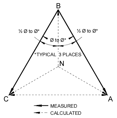
Open Delta PT phasors

Status
Not open for further replies.

mull982

Senior Member
I have been working with a power meter recently that has the voltage inputs from an "Open Delta" 3-wire PT arrangement. When I'm looking at the metering mode of the relay I can see all of the L-L voltage readings shown on the meter (4.16kV) However when I'm using the trigger trace function of the meter and the meter is displaying raw data I can only see waveforms for Va and Vc and see nothing for Vb.

When asking Multilin about this (Multilin PQMII Meter) they give me the following explanation: "On an 2PT open-delta the only two voltages that are derived from the power system are Vab and Vcb. With these two avaliable the meter calculates the thrid missing voltage Vca by vectorally adding the two measured voltages. The metering screen is thus displaying only a calculated value for the third Vca voltage."

Is this correct? If you know two voltage phasors can you add them to calculate the third?

I understand the use of the phasor Vab, but why is Vcb used instead of Vbc? I always thought that Vbc was used for the "Vb" or second voltage phasor?

When looking at the raw data in the trigger trace function it shows single Va, Vb, and Vc phasors with L-L values. It used this single L-N nomenclature except they are actually L-L voltage phasors. There are waveforms that appear for Va and Vc but not for Vb. They are saying that this is the one that is calculated and that it is not shown as part of the raw voltage data. However if Vca is the phasor that is calculated according to their statement above, then why would Vb be the missing phasor on the waveform plot as opposed to Vc?

Can anyone help clear this up?
 

Smart $

Esteemed Member
Location
Ohio
I have been working with a power meter recently that has the voltage inputs from an "Open Delta" 3-wire PT arrangement. When I'm looking at the metering mode of the relay I can see all of the L-L voltage readings shown on the meter (4.16kV) However when I'm using the trigger trace function of the meter and the meter is displaying raw data I can only see waveforms for Va and Vc and see nothing for Vb.

When asking Multilin about this (Multilin PQMII Meter) they give me the following explanation: "On an 2PT open-delta the only two voltages that are derived from the power system are Vab and Vcb. With these two avaliable the meter calculates the thrid missing voltage Vca by vectorally adding the two measured voltages. The metering screen is thus displaying only a calculated value for the third Vca voltage."

Is this correct? If you know two voltage phasors can you add them to calculate the third?
Yes.

OpenDeltaPTs.gif


I understand the use of the phasor Vab, but why is Vcb used instead of Vbc? I always thought that Vbc was used for the "Vb" or second voltage phasor?
Your understanding is correct. However, the reference to Vcb is just to denote that the common connection of the open delta PT's is "b". The phasors are added either Vab + (-Vcb) or (-Vab) + Vcb.

When looking at the raw data in the trigger trace function it shows single Va, Vb, and Vc phasors with L-L values. It used this single L-N nomenclature except they are actually L-L voltage phasors. There are waveforms that appear for Va and Vc but not for Vb. They are saying that this is the one that is calculated and that it is not shown as part of the raw voltage data. However if Vca is the phasor that is calculated according to their statement above, then why would Vb be the missing phasor on the waveform plot as opposed to Vc?
This part I can't answer. I'm in agreement with your line of thinking :D
 
Last edited:

mull982

Senior Member
OpenDeltaPTs.gif


Your understanding is correct. However, the reference to Vcb is just to denote that the common connection of the open delta PT's is "b". The phasors are added either Vab + (-Vcb) or (-Vab) + Vcb.

Can you refresh my memory how you add a negative vector? Is this simply the same as just subtracting the two vectors? Is subtraction what we are after when trying to calculate the missing phase.

To change from for instance a Vcb to Vbc all we simply do is reverse the direction of the vector correct? So what would happen instead of adding -Vcb as you mentioned we added Vbc? Would we get the same answer. Can you explain quickly the reason why the particular vectors are used as you mentioned for calculating.

So I guess for calculating the L-N voltages it just take half of the measured angle between the vectors and calcultates magnigutes to intersection point?

Why must the third L-L voltage be calculated with this PT arrangement? If it can physically be measured with a meter ( I can measure 120V between all 3 L-L connections) then why must it be calcuated as opposed to being measured directly?
 

mull982

Senior Member
Something else I noticed today when using using a fluke 1735 power meter. The meter was setup as a 3-Element Delta power network however we were only meausing a single phase 480V L-L circuit on a 3 phase system.

Whe measuring we have voltage probes V1 and V2 on both of the lines with V3 not connected to anything.

With this setup we have the V1-3 measured at 480V as expected but the other V2-3 and V3-1 voltages are shown as 277V or the L-G voltage. With the third V3 probe not connected why would it show L-G readings for the other two voltages instead of "0" Is this something it is calculating.

If I setup the meter for a wye power network it shows L-G voltages for V1 and V2 and it shows 20V for V3. I guess this 20V is just noise or some floating voltage?
 

Smart $

Esteemed Member
Location
Ohio
Can you refresh my memory how you add a negative vector? Is this simply the same as just subtracting the two vectors? Is subtraction what we are after when trying to calculate the missing phase.
Adding a negative vector is the same as subtracting a positive vector... the signs are the same as basic arithmetic. So if we retain "b" as the common connection of PT's and base are voltage vectors as such, yes we would subtract vectors to calculate the non-sampled voltage.

To change from for instance a Vcb to Vbc all we simply do is reverse the direction of the vector correct? So what would happen instead of adding -Vcb as you mentioned we added Vbc? Would we get the same answer. Can you explain quickly the reason why the particular vectors are used as you mentioned for calculating.
Yes, reversing the letters (reference point) is the same as negating or reversing the direction of the vector. If instead of adding a positive vector we added its negated vector, we would not get the same answer. Both the magnitude and direction would be wrong for any two vectors that are not at 90? to each other... and when they are 90? to each other, the magnitude would be correct but the direction would be wrong.

Using these two vectors over any of the other two possible combinations is just an arbitrary choice when using open-delta PT's.

So I guess for calculating the L-N voltages it just take half of the measured angle between the vectors and calcultates magnigutes to intersection point?
I'm fairly certain that's how it's done when L-N voltages are not sampled.

Why must the third L-L voltage be calculated with this PT arrangement? If it can physically be measured with a meter ( I can measure 120V between all 3 L-L connections) then why must it be calcuated as opposed to being measured directly?
Well in a sense, all voltage measurements are calculated... just with this arrangement we are using three points rather than two.

For example, say we connected two 12VDC batteries in series. We can measure across each and get 12 volts and we know from the dual battery configuration that to measure across both we will get 24 volts. With two meters we can measure each battery simultaneously, and with a third meter, we could verify that the other two measures add up to the third's.

The only difference here is that these are AC voltages, at the same frequency but out-of-phase to each other. By determining through calculation (actually by sample comparison) we can determine the extent of the out-of-phase relationship, and then through calculation the measure of third voltage and its phase relationship to the other two. Experience has taught us this is a viable method of measuring the third unsampled voltage.
 

Smart $

Esteemed Member
Location
Ohio
Something else I noticed today when using using a fluke 1735 power meter. The meter was setup as a 3-Element Delta power network however we were only meausing a single phase 480V L-L circuit on a 3 phase system.

Whe measuring we have voltage probes V1 and V2 on both of the lines with V3 not connected to anything.

With this setup we have the V1-3 measured at 480V as expected but the other V2-3 and V3-1 voltages are shown as 277V or the L-G voltage. With the third V3 probe not connected why would it show L-G readings for the other two voltages instead of "0" Is this something it is calculating.

If I setup the meter for a wye power network it shows L-G voltages for V1 and V2 and it shows 20V for V3. I guess this 20V is just noise or some floating voltage?
As you can only measure one voltage using two test points, apparently your power meter assumes a 30-120-30? relationship between L-L and L-N's. Perhaps because there is no direct third input. The 20V is probably from inductive coupling if it is not connected to anything. Try grounding the third probe, or connecting to X0 if ungrounded, and see what happens ;)
 

mull982

Senior Member
Yes, reversing the letters (reference point) is the same as negating or reversing the direction of the vector. If instead of adding a positive vector we added its negated vector, we would not get the same answer. Both the magnitude and direction would be wrong for any two vectors that are not at 90? to each other... and when they are 90? to each other, the magnitude would be correct but the direction would be wrong.

So what if instead of a -Vcb I added Vcb? I guess I would have an 120deg angle and the resultant vector would be too big?

What if instead of -Vcb I added Vbc? Woudn't that still give me a 60deg angle between the two vectors and give me the correct resultant Vca vector?

When we sum all voltage or currents at a given node we know they sum to zero. To do this we add all them all vectorally by adding Vab + Vbc + Vca to equal zero (assuming all are equal and balanced) So following this suit why wouldn't we use Vbc for the second vector as I asked above?
 

Smart $

Esteemed Member
Location
Ohio
So what if instead of a -Vcb I added Vcb? I guess I would have an 120deg angle and the resultant vector would be too big?
Exactly.

What if instead of -Vcb I added Vbc? Woudn't that still give me a 60deg angle between the two vectors and give me the correct resultant Vca vector?
Exactly ;)

When we sum all voltage or currents at a given node we know they sum to zero. To do this we add all them all vectorally by adding Vab + Vbc + Vca to equal zero (assuming all are equal and balanced) So following this suit why wouldn't we use Vbc for the second vector as I asked above?
Doesn't matter if they are equal and balanced... or not. The reason for the monitoring to begin with is because they may not be.

-Vcb = Vbc for the purpose at hand. So you are using Vbc, or -Vcb, just like adding a -1 to any number is the same as subtracting 1 from any number. It shouldn't be a difficult concept to digest if you passed whatever grade it is they taught negative numbers in addition and subtraction :D
 
Status
Not open for further replies.
Top