Open Service Neutral GFCI/RCD Detector

Status
Not open for further replies.

kwired

Electron manager
Location
NE Nebraska
In addition to the home that he is trying to improve (in the context of poor installation standards) there is also a commercial building, where the neutral was in fact brought to the service.

The only '120V' load in this commercial building is a surge protective device which is connected l-l and l-n.

IMHO better than trying to detect the open neutral is to find a surge protective device which will tolerate an open neutral and still function.

-Jon
We have a lot of equipment in North America that has surge protection from line to line, line to neutral, line to ground, even neutral to ground. Seldom will we ever know if the EGC is intact unless specifically testing for it.

That said his device should tolerate an open neutral just fine, it just won't clamp anything to N if the N is open.
 

mbrooke

Batteries Included
Location
United States
Occupation
Technician
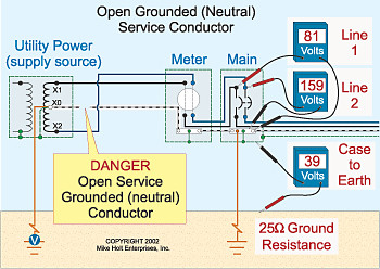
https://www.mikeholt.com/mojonewsarchive/NEC-HTML/HTML/DangerofOpenServiceNeutral~20020816.htm


"If the grounded (neutral) service conductor is opened or not provided at all, objectionable neutral current will flow on metal parts of the electrical system and dangerous voltage will be present on the metal parts providing the potential for electric shock"

JrHOG5.jpg


The utility company told me this is the main reason we omitted the use of neutral and 120v in the Philippines even when USA designed our power system with similar centertap configuration because we don't have the discipline to follow all the codes. And the death from open service neutral can be more than ground fault electrocution. It's not because its illegal to use 120v but more of safety.

So I avoided using 120v too in my parents house (most switching adaptors in most gadgets nowadays and even entertainment units like TV or home theater use universal 100-240v so anyone can use in any part of the world).

Yesterday I realized we have one 120v unit installed that I didn't consider before! In our commercial building, we have full 3-wire so have access to the neutral in the service entrance and main panel. And Equipment Grounding Conductor and stuff is readily available. All my questions before is related to my parents home where there is no 3-wire in the entire townhouse compound with other 5 houses. Many new commercial building are 3 wire but not normal homes.

I bought a Siemens First Surge 140,000A Surge protector a few months back after a 65 year old EE advised me how to use it locally, and installed it in the commercial building.

https://www.amazon.com/Siemens-FS14...F8&qid=1544142905&sr=8-1&keywords=first+surge

sYOCVk.jpg


t10B1e.jpg


The above was the Siemens First Surge installed in a subpanel with bolt-on breakers. It was just temporary setup. The proper way is to install it at the right side so the ground/neutral leads would be as short as possible.
Now here is the problem.

If the service neutral becomes open or disconnected. The electricity will reach all the metal enclosure in the building because the neutral and ground is bonded at the main panel (My connection in the office building is USA style with centertapped grounded neutral connected to the building and bonded with ground once and 120v, 240v available). This is how I power the Siemens First Surge which require 120v to operate and not 240v or it would burst into flame.

Now can you think of ways to integrate GFCI or RCD so that if the neutral got disconnected, the Siemens First Surge would lose power?

I saw someone make an open service neutral detector:

https://www.thaivisa.com/forum/topic/457002-the-hazard-of-an-open-circuit-neutral/

YA3zVq.jpg


Or without reading them. Just imagine the neutral part of the toroid differential circuit, if the neutral got disconnected.. think of a way it can disconnect the circuit by right connections of them all.

Plof0G.png


Ok to use isolation transformer in conjunction with the SPD and GFCI/RCD. But I have to make sure the unique connections will work and verifying with many before letting the master qualified electrician install any.
Thank a lot.

Perhaps the Philippines should consider TT earthing?


Either way, even in countries where code is enforced and followed, an open service neutral is still a very real hazard. Sometimes a break is unavoidable.

Going to 230 volts is a great idea, for many other reasons in addition to that.
 

Adamjamma

Senior Member
ok, as I said, the neutral has to be created as like a T T system in europe, by putting a main ground in the home and using it as the neutral point as well. Then, the Double Pole GFCI neutral is run from the breaker to the neutral bar. This then creates the sense circuit needed for the gfci to work, but only if your grounds are also run, as I stated. In fact, Seimans is where I got the information on the double pole wiring and how it can be done if a home had no grounds run, to protect a circuit, and how to run a 240 volt circuit as wired in the USA with no neutral running back to the panel.

But, because you are still running a split 120 system to create your 240 volt system you cannot use European RCD systems to try to protect it as they are designed for a single phase single pole 240 volt system not a center grounded split 120v type of 240 v system. Seimans owns European companies as well, and has quite a decent amount of information on their various websites plus they have a decent amount of technical help as well, and since I work in Jamaica a lot with similar problems, I have been in touch with them quite a bit and watch their equipment for new ideas.

So, since you only have live wires coming into your home, you need to create the ground and the neutral. But, you probably have a ground already in the foundation rebar and just do not realize it. By running to this from your main panel and rewiring so that you have grounds and neutrals in your outlets, you can both use gfci and use 120 volt circuits as needed.
Unfortunately, so far, I do not see a way of placing a 100 amp 100ma RCD in your panel as a main breaker as you would need a double pole version with a neutral as well... and I do not recall seeing one in any of the cataloques here... only the single pole with neutral and the three phase with neutral. in all these cases you would still need to create the ground and neutral point at the main panel buy getting a main ground.
 
Location
NE (9.06 miles @5.9 Degrees from Winged Horses)
Occupation
EC - retired
ok, as I said, the neutral has to be created as like a T T system in europe, by putting a main ground in the home and using it as the neutral point as well. Then, the Double Pole GFCI neutral is run from the breaker to the neutral bar. This then creates the sense circuit needed for the gfci to work, but only if your grounds are also run, as I stated. In fact, Seimans is where I got the information on the double pole wiring and how it can be done if a home had no grounds run, to protect a circuit, and how to run a 240 volt circuit as wired in the USA with no neutral running back to the panel.

But, because you are still running a split 120 system to create your 240 volt system you cannot use European RCD systems to try to protect it as they are designed for a single phase single pole 240 volt system not a center grounded split 120v type of 240 v system. Seimans owns European companies as well, and has quite a decent amount of information on their various websites plus they have a decent amount of technical help as well, and since I work in Jamaica a lot with similar problems, I have been in touch with them quite a bit and watch their equipment for new ideas.

So, since you only have live wires coming into your home, you need to create the ground and the neutral. But, you probably have a ground already in the foundation rebar and just do not realize it. By running to this from your main panel and rewiring so that you have grounds and neutrals in your outlets, you can both use gfci and use 120 volt circuits as needed.
Unfortunately, so far, I do not see a way of placing a 100 amp 100ma RCD in your panel as a main breaker as you would need a double pole version with a neutral as well... and I do not recall seeing one in any of the cataloques here... only the single pole with neutral and the three phase with neutral. in all these cases you would still need to create the ground and neutral point at the main panel buy getting a main ground.

I do not believe the CEE can be used as a normally current carrying method for 120v appliances. That is an earth return and is not allowed.
 

Adamjamma

Senior Member
I do not believe the CEE can be used as a normally current carrying method for 120v appliances. That is an earth return and is not allowed.

actually, in the USA you are correct... and it was allowed but was not as safe as the neutral coming from the transformers which was why even in the rural areas it has been disallowed now.. a safety factor.

In the UK it is frowned upon but you sometimes run into it.. a T-T system... where you only have the ground on site from whatever ground you create using the ground rods... and so the standard is now to use an RCD at the front end to help the ground and neutral. But it is not actually wanted so if at all possible you are taught to get a proper system installed. The talk is that Europe will actually put out a code change outlawing it all together... but as of now, a big RCD at the front of the system and tighter RCBOs is the usual practice of getting through it, even though the Ze is still too high for proper tripping of the breakers... apparently, the RCD will trip the system even if the breaker does not...

I am not an expert, that is just what my textbooks here are saying...

In this guys case, they have the USA split transformers and are only using 230 or 240 volt circuits.. no proper grounds no proper neutral... in a majority of the country. Since this is a country that has so many other problems according to papers, not so sure that adherence to the NEC is really all that big a priority but the person is trying to make his home and his parents home safer so... use any trick that might work... using the tricks of a T T system might help make the system safer.

However, in my own case, even with my limited knowledge, I would never ever want to have a system like the person here has, with the no neutral or ground connecting to the main transformers... yet somehow, through all the storms and such, they do not have as many deaths from electrocution reported as one would expect from using improperly grounded 240 volt systems with no neutrals.
 

Sahib

Senior Member
Location
India
If proper bonding exists, open neutral may not cause a safety hazard, IMO. Lights blinking could alert about the open neutral existence.
 

mbrooke

Batteries Included
Location
United States
Occupation
Technician
ok, as I said, the neutral has to be created as like a T T system in europe, by putting a main ground in the home and using it as the neutral point as well. Then, the Double Pole GFCI neutral is run from the breaker to the neutral bar. This then creates the sense circuit needed for the gfci to work, but only if your grounds are also run, as I stated. In fact, Seimans is where I got the information on the double pole wiring and how it can be done if a home had no grounds run, to protect a circuit, and how to run a 240 volt circuit as wired in the USA with no neutral running back to the panel.

But, because you are still running a split 120 system to create your 240 volt system you cannot use European RCD systems to try to protect it as they are designed for a single phase single pole 240 volt system not a center grounded split 120v type of 240 v system. Seimans owns European companies as well, and has quite a decent amount of information on their various websites plus they have a decent amount of technical help as well, and since I work in Jamaica a lot with similar problems, I have been in touch with them quite a bit and watch their equipment for new ideas.


I disagree, a European RCD should work. Its only looking for unbalance, it does not care that both legs are live vs one live and one grounded.
 

mbrooke

Batteries Included
Location
United States
Occupation
Technician
actually, in the USA you are correct... and it was allowed but was not as safe as the neutral coming from the transformers which was why even in the rural areas it has been disallowed now.. a safety factor.

In the UK it is frowned upon but you sometimes run into it.. a T-T system... where you only have the ground on site from whatever ground you create using the ground rods... and so the standard is now to use an RCD at the front end to help the ground and neutral. But it is not actually wanted so if at all possible you are taught to get a proper system installed. The talk is that Europe will actually put out a code change outlawing it all together... but as of now, a big RCD at the front of the system and tighter RCBOs is the usual practice of getting through it, even though the Ze is still too high for proper tripping of the breakers... apparently, the RCD will trip the system even if the breaker does not...

I am not an expert, that is just what my textbooks here are saying...

In this guys case, they have the USA split transformers and are only using 230 or 240 volt circuits.. no proper grounds no proper neutral... in a majority of the country. Since this is a country that has so many other problems according to papers, not so sure that adherence to the NEC is really all that big a priority but the person is trying to make his home and his parents home safer so... use any trick that might work... using the tricks of a T T system might help make the system safer.

However, in my own case, even with my limited knowledge, I would never ever want to have a system like the person here has, with the no neutral or ground connecting to the main transformers... yet somehow, through all the storms and such, they do not have as many deaths from electrocution reported as one would expect from using improperly grounded 240 volt systems with no neutrals.

I think he is referring to using the earth for continuous 120 volts vs clearing a fault.
 

GoldDigger

Moderator
Staff member
Location
Placerville, CA, USA
Occupation
Retired PV System Designer
One other side track from your overall situation:
The operation of a surge protective device depends on its being able to shunt away any voltage spikes above a certain level with a very low resistance, making a voltage divider with the source impedance of the fault that is causing the voltage excursion. That means that the SPD needs to have the absolute minimum impedance between it and the protected circuit conductors.
A transformer, even an autotransformer, will represent a relatively large impedance on the scale of an operating SPD.
With only one nominal 120V SPD to work with you will not be able to protect your 240V wiring and its connected loads.
If you had a way to run a solid metal path between the service transformer secondary at the pole and the location of your SPD(s) you would be able to use 120V SPDs in a symmetric circuit on either side to the line to that neutral/ground wire.
Just a ground electrode will give you little or no effective SPD operation unless you run two 120V SPDs symmetrically to that ground electrode or a single 240V SPD between the hot wires with no neutral/ground connection.

When your appliances have no earth connection to their chassis a fault inside that appliance can bring the chassis to as much as 120V with respect to ground, and even with no deliberate ground connections anywhere in the house there will be grounded surfaces from metal piping, concrete floors, and other incidental paths to earth. Connecting all of the appliance chassis together without also connecting them to a solid path back to the transformer secondary risks just energizing all of them when one faults. It is true that if you were to add an RCD to that scenario it would be more likely that a fault would cause a trip before you had a chance to be shocked yourself. But a 100ma threshold RCD would not provide any effective life safety protection if the resistance between the chassis and ground (before you enter the circuit) is too high.
 

Adamjamma

Senior Member
I disagree, a European RCD should work. Its only looking for unbalance, it does not care that both legs are live vs one live and one grounded.

according to both Seimens and Hager have told me that I cannot use their RCDs on USA style 240 volt circuits because there would be too many false trips due to the way the 240 volts is created. but they also have given me the spec sheets to use the same rcds and rcbos on 110 volt circuits with a normal neutral. So, apparently, there is a difference and they said most of the tripping problems happen not from imbalance in the live wire as much as feedback from ...other live wires being used...

Again, I am not totally understanding it but they also said that unless you use a 2 pole plus neutral RCD or RCBO false tripping will occur and often from other circuits interference not the actual circuit, if one is using one live to neutral position in order to create a higher voltage. But, a 2pole plus neutral is not a normal, in Europe, configuration.
Now, since I am a student and not understanding all the theory, all I can do is say what I have been told in my several letters and emails to them...
 

RumRunner

Senior Member
Location
SCV Ca, USA
Occupation
Retired EE
That image is one I randomly took at internet showing what is a GFCI/RCD. This is in order to inquire what this description mean:

sgzXRB.jpg


"How it works.
Consider normal operation (top diagram), the neutral is at or near ground potential so no current flows down the ground stake and the RCD remains in balance. Open the neutral (second diagram), now there is no current in the neutral leg of the RCD and it opens protecting your supply. Reverse phase and neutral (third diagram) and we have a similar effect, again the RCD is imbalanced and trips."


This is taken from the thai site:

https://www.thaivisa.com/forum/topic/457002-the-hazard-of-an-open-circuit-neutral/


What does it mean? How do you understand it? Kindly explain how the circuit can detect open service neutral and how you can do it with the USA 120/240v split power ac system.

Tersh,

Referring to the middle schematic diagram-- your theory holds. However, in the real world-- electronics/electricity doesn't behave exactly what you have envisioned.

The instance you cut the wire that is grounded (the one indicated with an “X”) with color blue-- the current passing through the inductor that is being compared with the top (brown) wire will see a change in current. During this split-second exigency, power will also be lost.


With its blue wire losing its connection to the lower inductor -- which WAS connected to ground—the RCD will not have the chance to compare this current that it was seeing before the wire was severed.

For this RCD to function without false alarm, it needs a wee time delay to ignore tripping caused by transient disturbances. . . otherwise you will be inundated with nuisance shutdowns. It needs to discriminate between the good and the bad signal.

Now, you can argue that the (MEN) multiple earth neutral will provide the continuity of power through the multiple ground connection, and (hopefully) enable the RCD to function and open the contacts.

The problem with this is, earth is an unreliable conductor whose resistance could vary depending on the moisture content.
And besides, it is an unorthodox even insane- not an acceptable and totally unsound engineering practice.

If you had driven these rods in the infiniteness of moist ground like a rice field in the Philippines, you will probably see a uniform impedance, but it will still not pass muster in a sensible engineering practice.

Now, the third diagram with the REVERSED HOT to NEUTRAL scenario is even worst.

If you reverse the BLUE and BROWN as indicated in your drawing -- you would end up connecting the hot brown wire (and while at the same time) keeping the MEN connected the way they are-- you'd be creating a short circuit.

Try tracing it systematically and you'll see what I'm talking about.

Note:
I'm not endorsing anything that could compromise safety. Hiring a multi- licensed electrician will not absolve you from any consequences that may arise should you go ahead with what you think would achieve your goal.

Don't call Jacoby and Myers telling them that Myspark, told you how it should be done. I'm just answering your question.

Mabuhay! :D
 

mbrooke

Batteries Included
Location
United States
Occupation
Technician
according to both Seimens and Hager have told me that I cannot use their RCDs on USA style 240 volt circuits because there would be too many false trips due to the way the 240 volts is created. but they also have given me the spec sheets to use the same rcds and rcbos on 110 volt circuits with a normal neutral. So, apparently, there is a difference and they said most of the tripping problems happen not from imbalance in the live wire as much as feedback from ...other live wires being used...

It's impossible to know what they were referring to. Theoretically at 120 volt line to ground you will have less current leakage then 230 volt line to ground- so all the same like circuit length and insulation 120 volts line to ground will be more secure.


Again, I am not totally understanding it but they also said that unless you use a 2 pole plus neutral RCD or RCBO false tripping will occur and often from other circuits interference not the actual circuit, if one is using one live to neutral position in order to create a higher voltage. But, a 2pole plus neutral is not a normal, in Europe, configuration.
Now, since I am a student and not understanding all the theory, all I can do is say what I have been told in my several letters and emails to them...


If you want to RCD a 120/240 volt system with both 120 and 240 volt loads I see no reason why a 3 pole 3 phase IEC RCD will not work out.

For center tapped 240, a standard 230 volt IEC RCD should work just fine.

Just make sure that in any case the test resistor circuit has 240 volts potential across it so the right current is passed through to toroid when when the test button is depressed.
 

tersh

Senior Member
Location
new york


I'd like to know what exactly Mike Holt mean in https://www.mikeholt.com/mojonewsarc...l~20020816.htm by

"If the grounded (neutral) service conductor is opened or not provided at all, objectionable neutral current will flow on metal parts of the electrical system and dangerous voltage will be present on the metal parts providing the potential for electric shock."

Does the following scenario described what he meant. Well say you lost the neutral in your service entrance (from Hurricine, earthquake, thief, etc.). And you are staying at the third floor of your house. You turn on the 120v metal bread toaster (or any appliance). Since there is no neutral return. Then the current can't leave the main panel. Instead, it will seek the neutral bus bar to ground bus bar in your main panel and from the ground bus bar goes through the ground wire straight to your toaster metal enclosure (Egc). And when you touch the metal with bare hand standing on bare feet. Then the current would use your body as return current back to the building concrete and to utility centertap. This could happen if the service neutral got cut by accident or intentionally right?
Was this what Mike Holt meant?

Well. In the office building with 3-wire. There is no 120v appliance except 120v Leviton surge protector connected to 240-120v step down transformer. Purpose is to take advantage of lower VPR (Voltage Protection Rating). And I'm not interested in asking the electrician to activate the ground wire as 120v anymore because of the hazard. I don't take any chances. So I'm just interested in open neutral as theoretical and for knowledge when I return to the US where neutral is used for 120v.


tersh

Senior Member
Location
new york
ok, as I said, the neutral has to be created as like a T T system in europe, by putting a main ground in the home and using it as the neutral point as well. Then, the Double Pole GFCI neutral is run from the breaker to the neutral bar. This then creates the sense circuit needed for the gfci to work, but only if your grounds are also run, as I stated. In fact, Seimans is where I got the information on the double pole wiring and how it can be done if a home had no grounds run, to protect a circuit, and how to run a 240 volt circuit as wired in the USA with no neutral running back to the panel.

I'm not trying to use European Double Pole GFCI because of their lack of this feature of UL 2015 requirement that all GFCIs in the USA need automatic circuit based self-test.

I'm using the USA Siemens SF230A 2-pole GFIC Breaker precisely because of that. You can even use it in Europe by simply connecting a tiny 10w autotransformer to power its 120v internal circuitry.

dYivjT.jpg


Someone familiar with Siemens taught me how to connect it that way. Can you see something wrong with it (especially if used long term)? It works flawlessly when I asked the qualified electrician to test it.

About the automatic circuit based self test. No. It's not about pressing the white button manually, but something in the circuit itself that can test itself. Here's the summary of it.

I2ySt8.png


It looks like it works just as the test switch, except the current stays lower than the trip threshold and it measures the feedback of the coil. It only self-tests the sensing part of the GFCI. Not the breaker part.

I can't find a single receptacle that is 240v that can test itself. Do you happen to know of any?

This is why I have to get into the difficult path of buying 6 pcs of Siemens GFCI 2-pole breakers (with automatic self tests) and install this in a 12 space Siemens sub-panel. Qualified electrician still hasn't installed it because waiting for Siemens Engineering testing of all present stock of their 2-pole GFCI to see if there is a need to recall all of them.

I learnt also that the RCDs (Residual Current Devices) in Europe don't have the sophisticated self tests as the GFCIs in the United States, so all 240v RCDs in Europe don't have the capacity to test itself. Nowhere else have it except USA. I've been looking for quite a while. Here's a bit of the UL requirements in 2015 :

https://images.homedepot-static.com/catalog/pdfImages/9b/9b2ff02a-bbe7-4d36-8814-dddebdc02136.pdf

"Underwriters Lab (UL) 943 requires that a Self Test and Lockout feature be included in all GFCI circuit breaker devices manufactured after June 29th, 2015. Testing GFCIs on a monthly basis is a good idea that is sometimes forgotten. UL suggests GFCI devices be tested every 30 days after installation to ensure they are properly working. Now the new Self Test and Lockout feature enables the GFCI circuit breaker to automatically and continuously test itself to ensure that it is working properly. If it is detected that the device has been compromised, the device trips itself and locks out the homeowner from resetting the device, reducing the possibility of the homeowner incorrectly assuming that the device was tripped to prevent a ground fault. This will help guarantee the best protection is given to your home at all times. "


But, because you are still running a split 120 system to create your 240 volt system you cannot use European RCD systems to try to protect it as they are designed for a single phase single pole 240 volt system not a center grounded split 120v type of 240 v system. Seimans owns European companies as well, and has quite a decent amount of information on their various websites plus they have a decent amount of technical help as well, and since I work in Jamaica a lot with similar problems, I have been in touch with them quite a bit and watch their equipment for new ideas.

So, since you only have live wires coming into your home, you need to create the ground and the neutral. But, you probably have a ground already in the foundation rebar and just do not realize it. By running to this from your main panel and rewiring so that you have grounds and neutrals in your outlets, you can both use gfci and use 120 volt circuits as needed.
Unfortunately, so far, I do not see a way of placing a 100 amp 100ma RCD in your panel as a main breaker as you would need a double pole version with a neutral as well... and I do not recall seeing one in any of the cataloques here... only the single pole with neutral and the three phase with neutral. in all these cases you would still need to create the ground and neutral point at the main panel buy getting a main ground.
 
Last edited:

tersh

Senior Member
Location
new york
Tersh,

Referring to the middle schematic diagram-- your theory holds. However, in the real world-- electronics/electricity doesn't behave exactly what you have envisioned.

The instance you cut the wire that is grounded (the one indicated with an “X”) with color blue-- the current passing through the inductor that is being compared with the top (brown) wire will see a change in current. During this split-second exigency, power will also be lost.


With its blue wire losing its connection to the lower inductor -- which WAS connected to ground—the RCD will not have the chance to compare this current that it was seeing before the wire was severed.

For this RCD to function without false alarm, it needs a wee time delay to ignore tripping caused by transient disturbances. . . otherwise you will be inundated with nuisance shutdowns. It needs to discriminate between the good and the bad signal.

Now, you can argue that the (MEN) multiple earth neutral will provide the continuity of power through the multiple ground connection, and (hopefully) enable the RCD to function and open the contacts.

The problem with this is, earth is an unreliable conductor whose resistance could vary depending on the moisture content.
And besides, it is an unorthodox even insane- not an acceptable and totally unsound engineering practice.

If you had driven these rods in the infiniteness of moist ground like a rice field in the Philippines, you will probably see a uniform impedance, but it will still not pass muster in a sensible engineering practice.

Now, the third diagram with the REVERSED HOT to NEUTRAL scenario is even worst.

If you reverse the BLUE and BROWN as indicated in your drawing -- you would end up connecting the hot brown wire (and while at the same time) keeping the MEN connected the way they are-- you'd be creating a short circuit.

Try tracing it systematically and you'll see what I'm talking about.

Note:
I'm not endorsing anything that could compromise safety. Hiring a multi- licensed electrician will not absolve you from any consequences that may arise should you go ahead with what you think would achieve your goal.

Don't call Jacoby and Myers telling them that Myspark, told you how it should be done. I'm just answering your question.

Mabuhay! :D

Yes. It's obvious that if you cut the neutral or any of the source power supply of the GFCI. It circuitry shuts off and it won't even trip it (at least the Siemens SF230A 2-pole Breaker which I told the electrician to test and it won't trip when power shuts down from source). Since the link describes using ordinary GFCI/RCDs. How do they still maintain the power of the unit? Any ideas?

Btw.. No. I won't attempt to use any open service neutral detector anymore. I just realized MEN means "Multiple Earth Neutral". I googled it before and "Mense" came up so didn't understood the diagram (I do now thanks to you). I just need knowledge of any device in the US to detect open service neutral when I return to the US. I just rented a place, I guess the easiest detector is simply seeing if your 120v lamp is flickering or very weak already (it means it's not using the neutral from the utility but using ground path).
 

tersh

Senior Member
Location
new york
One other side track from your overall situation:
The operation of a surge protective device depends on its being able to shunt away any voltage spikes above a certain level with a very low resistance, making a voltage divider with the source impedance of the fault that is causing the voltage excursion. That means that the SPD needs to have the absolute minimum impedance between it and the protected circuit conductors.

You mentioned "That means that the SPD needs to have the absolute minimum impedance between it and the protected circuit conductors." But in UL requirement it's the other way around. Here:

https://standardscatalog.ul.com/standards/en/standard_1449_4

"Type 3 – Point of utilization SPDs, installed at a minimum conductor length of 10 meters (30 feet) from the electrical service panel to the point of utilization, for example cord connected, direct plug-in, receptacle type and SPDs installed at the utilization equipment being protected. See marking in 80.3. The distance (10 meters) is exclusive of conductors provided with or used to attach SPDs. "

The above was describing the 10 meters requirement from the SPD at equipment to the service panel. While you were mentioning that it need some impedance between the SDP and equipment. You mean one must run 20 meters of wire with the SPD in between??

(Guys. Please don't miss my 3 messages before this message with critical questions addressed to different people and all. Thanks.)


A transformer, even an autotransformer, will represent a relatively large impedance on the scale of an operating SPD.
With only one nominal 120V SPD to work with you will not be able to protect your 240V wiring and its connected loads.
If you had a way to run a solid metal path between the service transformer secondary at the pole and the location of your SPD(s) you would be able to use 120V SPDs in a symmetric circuit on either side to the line to that neutral/ground wire.
Just a ground electrode will give you little or no effective SPD operation unless you run two 120V SPDs symmetrically to that ground electrode or a single 240V SPD between the hot wires with no neutral/ground connection.

When your appliances have no earth connection to their chassis a fault inside that appliance can bring the chassis to as much as 120V with respect to ground, and even with no deliberate ground connections anywhere in the house there will be grounded surfaces from metal piping, concrete floors, and other incidental paths to earth. Connecting all of the appliance chassis together without also connecting them to a solid path back to the transformer secondary risks just energizing all of them when one faults. It is true that if you were to add an RCD to that scenario it would be more likely that a fault would cause a trip before you had a chance to be shocked yourself. But a 100ma threshold RCD would not provide any effective life safety protection if the resistance between the chassis and ground (before you enter the circuit) is too high.
 

Sahib

Senior Member
Location
India
Using SPD to protect against open neutral condition may not be appropriate because a SPD is for protecting against over voltages of very short duration and in trying to clear over voltage due to open neutral condition, a SPD may destroy itself.
 

tersh

Senior Member
Location
new york
Using SPD to protect against open neutral condition may not be appropriate because a SPD is for protecting against over voltages of very short duration and in trying to clear over voltage due to open neutral condition, a SPD may destroy itself.

Of course. No one uses SPD to protect against open neutral condition. They use RCDs. I heard there are GFCIs and RCDs where if the source power is gone, they open up??

For the Siemens SF230A 2-pole breakers. If the source power is removed. The breaker won't open up but stay closed. Has anyone come across any GFCI or RCD where it would open up upon lost of power, something where they power the contacts closed, and without control power, being spring loaded, they open?? Maybe these were the RCDs the Thai were describing.
 

GoldDigger

Moderator
Staff member
Location
Placerville, CA, USA
Occupation
Retired PV System Designer
You mentioned "That means that the SPD needs to have the absolute minimum impedance between it and the protected circuit conductors." But in UL requirement it's the other way around. Here:

https://standardscatalog.ul.com/standards/en/standard_1449_4

"Type 3 – Point of utilization SPDs, installed at a minimum conductor length of 10 meters (30 feet) from the electrical service panel to the point of utilization, for example cord connected, direct plug-in, receptacle type and SPDs installed at the utilization equipment being protected. See marking in 80.3. The distance (10 meters) is exclusive of conductors provided with or used to attach SPDs. "

The above was describing the 10 meters requirement from the SPD at equipment to the service panel. While you were mentioning that it need some impedance between the SDP and equipment. You mean one must run 20 meters of wire with the SPD in between??

(Guys. Please don't miss my 3 messages before this message with critical questions addressed to different people and all. Thanks.)


tersh: That section describes a *point of utilization* SPD. That means it is designed to be at the end of a branch circuit where the equipment to be protected. The limited power handling capacity if the SPD is most effective when there is a high impedance between the source (service wires) and the SPD, but minimal impedance between the SDP and the equipment it is protecting. Any added resistance between the SPD and the protection point (protected load at the end of the branch circuit) will reduce its effectiveness. So wherever it is connected the path to the SPD should be through a transformer.

Sent from my XT1585 using Tapatalk
 

tersh

Senior Member
Location
new york
tersh: That section describes a *point of utilization* SPD. That means it is designed to be at the end of a branch circuit where the equipment to be protected. The limited power handling capacity if the SPD is most effective when there is a high impedance between the source (service wires) and the SPD, but minimal impedance between the SDP and the equipment it is protecting. Any added resistance between the SPD and the protection point (protected load at the end of the branch circuit) will reduce its effectiveness. So wherever it is connected the path to the SPD should be through a transformer.

Sent from my XT1585 using Tapatalk

Ok. If you have a universal power supply that can accept 88v to 264v. Isn't it if you use a 120v SPD with VPR of 500v. It's more protective than using a 240v SPD with VPR of 1200?
 
Status
Not open for further replies.
Top