PF and Drives ?

Status
Not open for further replies.

Ingenieur

Senior Member
Location
Earth
Welded? This is off topic somewhat, but I thought the laminations had to be insulated from one another?

On a transformer yes

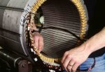
on a motor the iron lamnations for a given phase/pole are bonded for magnetic homogeneity
good flux gradient/consistency
 

Jraef

Moderator, OTD
Staff member
Location
San Francisco Bay Area, CA, USA
Occupation
Electrical Engineer

Attachments

  • Stator%20winding%20low.jpg
    Stator%20winding%20low.jpg
    103.2 KB · Views: 1

Ingenieur

Senior Member
Location
Earth
imagegif
0615_MotCtrl_F10.gif


Typical induction motor rotor (field) frame
the iron or laminations a bonded
the conductors are insulated (from frame and each other)
 

Mike01

Senior Member
Location
MidWest
cf

cf

Jraef, Ingenieur, Thanks for all the good info..Jraef since I am on the right coast I do not suppose you offer classes on-line......I will look to see what I can find around town, the interesting thing is I see all kinds of projects from all different firms in looking at some reference specifications for VFD's, and in the testing specifications not a word is mentioned as it relates to carrier frequency or what to set it at or who is responsible so now I am curious how these are set or if the mfgr. Rep just does this at start up. I assume for package equipment it is set by the manufacturer before shipping, but for projects where they are specified and installed under the electrical specifications for mechanical equipment [this is the majority of my world pumps and fans, wastewater, etc.] I have never seen the question asked [at least not to my knowledge]. You mention, “YOU decide the CF setting based on what you need to do” so I assume that someone has to determine this based on the specific load and operational parameters, drive type conductor length, etc.. “IF anything. The best practice is to leave it as low as you can live with, it's better for the drive and better for the circuit” what makes it better about leaving it low? It appears by leaving it low it will not “overwork the drive” requiring de-rating, but I imagine like previously indicated it sounds like a deeper topic in order to “dial it in for the application”. I tried looking at some manufacturers website but could not find guidelines or formulas for setting the carrier frequency so I will keep digging just trying to understand it all…good stuff thanks again everyone.
 

Jraef

Moderator, OTD
Staff member
Location
San Francisco Bay Area, CA, USA
Occupation
Electrical Engineer
Here's one way to look at it. Every VFD will be sent out from the factory with whatever the factory has decided is the default CF, which then ALSO means that the rating of the drive is based upon that setting. So for example below is a clip from an A-B PowerFlex 525 drive manual on setting their Carrier Frequency (A-B calls it PWM Frequency, same thing);
PF525 CF De-Rate.JPG
From the note below the chart you see that their CF is factory set at 4kHz. That means if you have a 10HP motor with a FLC of 14A and buy a drive rated for 17A, it is 17A at a 4kHz CF. If you increase the CF to 12kHz so that the boss can't hear the motor whine any more, you have to de-rate that drive to about 70%. So that 17A drive can now only handle a 11.9A load, which is a 7.5HP motor not a 10HP motor. If you want to use that same 10HP motor and have a CF of 12kHz, you need to buy a drive rated for at least 20A (14/.70), which in that product line means a 15HP drive, the next size up. But if you do nothing and nobody complains about the motor noise, you never had to touch the CF setting.

In addition, lets say I have that same 10HP motor and the boss is complaining, but you look at the motor under it's full expected load conditions and it never draws more than 11A. You can still go ahead and raise the CF to 12kHz to get the boss off your back, but you would then go in and set the maximum current setting of the drive at 11.9A as well, so the drive will protect itself.

Bottom line, there is more than one way to skin this cat, but in general, leaving the CF alone is the first course of action, because that's what the drive was designed for.

Case 2, different scenario (because this isn't a dramatic with small motors). Now let's say I have a PowerFlex 753 drive on a 100HP inverter duty motor that is 400ft. from drive to motor. A-B publishes a document for their drives (and it only relates to theirs, nobody else) showing the maximum distance from drive to motor before I must worry about standing wave issues. I have that chart and for this size PF753 at the factory default setting of 2khz (it's lower on larger drives), the maximum distance is 450ft. But if I turn up the CF to just 4khz, that maximum distance drops to 300ft before there are risks, and since I'm 400ft away, I now have to take additional measures, such as a dv/dt filter on the output. If I increase that CF to 12kHz, now my distance drops to just 60ft! That's again why I tell people that the best course of action is not not mess with the CF unless you have a SPECIFIC reason to, in which case you have to start looking at other causes and effects.
 

Ingenieur

Senior Member
Location
Earth
I never knew the fc was a field adjustable parameter
and I've played with 100's of drives
learn something new everyday

why derate? Due to increased temperatures due to the higher switching rate?
so lower current capability to maintain a max device temp?
 

GeorgeB

ElectroHydraulics engineer (retired)
Location
Greenville SC
Occupation
Retired
Thanks Jraef and Ingenieur, learned what I missed in my 1970 rotating machines course ... I still have the textbook and need to do some review. All I remember about induction motors is how the shorting bar shapes address slip and starting currents.
 

Ingenieur

Senior Member
Location
Earth
Ingenieur, just curious what software do you use for construction / modeling??

not really for construction but for education/verification
matlab/simulink, great for power electronics and control

plecs simulink plug-in

and a power program developed by the Canadian hydro utilities (Pscad) https://hvdc.ca/pscad/

I have some that came with this text, great stuff but overkill and difficult to use
https://www.crcpress.com/Computer-A...sis-Second-Edition/Kusic/p/book/9781420061062
had the author for the course, so we had to use it, tough course, started with 8, 3 of us finished

etap for std work deliverables
 
Last edited:

Besoeker

Senior Member
Location
UK
not really for construction but for education/verification
matlab/simulink, great for power electronics and control

plecs simulink plug-in

and a power program developed by the Canadian hydro utilities (Pscad) https://hvdc.ca/pscad/

I have some that came with this text, great stuff but overkill and difficult to use
https://www.crcpress.com/Computer-A...sis-Second-Edition/Kusic/p/book/9781420061062
had the author for the course, so we had to use it, tough course, started with 8, 3 of us finished
Over the years I have written various programs to simplify/automate routine calcs. This was to make it quicker for me but I had hoped to engage my colleagues and get some of the work load off me.
Speed, torque, PF, harmonics, panel cooling, heatsink temps, motor equivalent circuits...............stuff....
Somehow, it still all ended up on my desk.........
 

Jraef

Moderator, OTD
Staff member
Location
San Francisco Bay Area, CA, USA
Occupation
Electrical Engineer
... why derate? Due to increased temperatures due to the higher switching rate?
so lower current capability to maintain a max device temp?
Yes, exactly. The transistors will have a relatively fixed amount of switching losses, but the higher rate means more cumulative PU current losses. The heat sinks will be designed to radiate and dissipate the heat based on the losses at the stated maximum CF. Heat sinks are a very expensive part of a drive, and people tend to want smaller-cheaper-better with every successive generation, so this is one of the consequences.

25+ years ago as VFDs began to get affordable and popular, CF was not adjustable. Toshiba released what at the time were called their "quiet drives" that had an adjustable CF up to 10kHz in I think around 1990(?), which took the HVAC drives market by storm. That's because air handlers where the motor is inside of the air stream were conducting the motor whining sound down through the air ducts into quiet rooms and causing complaints. HVAC was and still is the largest market for VFDs, so when Toshiba's quiet drives took off it forced every other mfr to adapt or perish. Early versions of drives were over designed and had lots of extra heat sink, so de-rating wasn't as big of a deal at first. But every successive design generation began using smaller faster transistors with lower losses, yet less heat sink at the same time. So now we have adjustable CF even though most of the time we don't need it, on drives that are designed so close to the bone that they require de-rating if you turn it up.
 

Ingenieur

Senior Member
Location
Earth
Yes, exactly. The transistors will have a relatively fixed amount of switching losses, but the higher rate means more cumulative PU current losses. The heat sinks will be designed to radiate and dissipate the heat based on the losses at the stated maximum CF. Heat sinks are a very expensive part of a drive, and people tend to want smaller-cheaper-better with every successive generation, so this is one of the consequences.

25+ years ago as VFDs began to get affordable and popular, CF was not adjustable. Toshiba released what at the time were called their "quiet drives" that had an adjustable CF up to 10kHz in I think around 1990(?), which took the HVAC drives market by storm. That's because air handlers where the motor is inside of the air stream were conducting the motor whining sound down through the air ducts into quiet rooms and causing complaints. HVAC was and still is the largest market for VFDs, so when Toshiba's quiet drives took off it forced every other mfr to adapt or perish. Early versions of drives were over designed and had lots of extra heat sink, so de-rating wasn't as big of a deal at first. But every successive design generation began using smaller faster transistors with lower losses, yet less heat sink at the same time. So now we have adjustable CF even though most of the time we don't need it, on drives that are designed so close to the bone that they require de-rating if you turn it up.


Thanks
I sketched this out to convince myself
used area, could have used magnitude
the conduction rate/time increases with fc
yes, I have issues ;)
 
Last edited:

Mike01

Senior Member
Location
MidWest
Ingenieur, I apologize construction was the wrong word, yes looking for a software to play around with for my education interest I figure its cheaper than getting my hands on a drive / motor / scope and playing around [although that would be pretty kool], looking more at simulation and the associated wave forms..I like you drawings, just curious what is the 66/250 reference and the 26, 40, etc? if the bottom one is related to higher fc then it looks like you have potentially more "overshoot" resulting in higher harmonics as well?
 

Ingenieur

Senior Member
Location
Earth
Ingenieur, I apologize construction was the wrong word, yes looking for a software to play around with for my education interest I figure its cheaper than getting my hands on a drive / motor / scope and playing around [although that would be pretty kool], looking more at simulation and the associated wave forms..I like you drawings, just curious what is the 66/250 reference and the 26, 40, etc? if the bottom one is related to higher fc then it looks like you have potentially more "overshoot" resulting in higher harmonics as well?

In that case matlab/simulink

the number in the fc triangle signal is the graph sqares(area) under the ref f
the larger the area (or could have used the height from 0 to the ref f at the center of the fc signal) the wider the pulse, this is how long the igbt is fired
so the pulse associated with 26 is 26 wide and so on
as the numbers increase the pulse gets wider, igbt on longer
66 and 83 are the totals for each fc
the 1/2 wave is 250 units long (each grid is 10, 5 x 5 x 10)
66/250 and 83/250 is the total time current flows for each fc
basically 25% and 33% of the time

this is a simplification
the vfd controller does everything in signals/computations
but this the basic math
 
Status
Not open for further replies.
Top