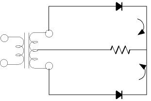
Positive or Negative Alternation of the sine wave developed across the load.

Status
Not open for further replies.

lbmcse

Member
Location
USA
Part of your confusion, I think, is that the arrows next to the resistor are showing electron flow, not "conventional" current.
Conventional current is drawn as if positive charges were moving.
The voltage across a resistor is proportional to the conventional current through it.
In the left picture conventional current is flowing counter-clockwise. That makes the top of the resistor negative, as shown in the wave at the end of line.

When you use conventional current, the flow through a diode is in the direction of the arrowhead in the symbol.

PS: Or else the arrow direction is just a mistake!

Sent from my XT1585 using Tapatalk

Sorry, GoldDigger. I should have replied to this. No, I'm going with electron flow, as that's what my text, and program "assume." I know neither has been disproven, but there you go. So electrons always flow against the arrow of a diode, in my neck of the woods, so to speak.
 

Smart $

Esteemed Member
Location
Ohio
All voltage measurements are referenced to ground.

Could you elaborate? I realize when taking a voltage reading that's not phase to phase, I'm measuring a voltage, "with reference to ground." I get that. Would you mind tying that in to my OP?

Thanks for taking the time, Smart.
Well technically, it wouldn't matter if the voltage was not referenced to ground... but it would have to be referenced to some point in the circuit. In this case, it is referenced to the lower "rail", which is bonded to ground.

What does matter is that the voltage is positive with respect to the reference for a half cycle and negative for the other half cycle. When the diode blocks current, there is no voltage measured at the upper right node, i.e. it is at the same potential as the reference. While the diode is forward biased, the voltage measured is a result of conducting current during the positive half cycle or the negative half cycle.
 

ggunn

PE (Electrical), NABCEP certified
Location
Austin, TX, USA
Occupation
Consulting Electrical Engineer - Photovoltaic Systems
Something I just learned in that electron tube class I am taking (which started with tube diodes) is that the "arrow" in a diode symbol isn't an arrow at all. Early tube diodes had a self heating filament as a cathode and a plate as an anode. The cathode was bent at a sharp angle with the middle point oriented toward the plate, and electrons boiled off the hot cathode and jumped across to the anode during forward bias. The diode symbol is a representation of the bent cathode and the anode plate, and current flows in the direction of the "arrow" only if you use electron flow as the convention for current direction.
 

kwired

Electron manager
Location
NE Nebraska
Only if your current arrows follow electron flow. Conventional positive to negative current flows opposite to your arrows.
I don't think OP is stuck on electron flow vs.conventional flow, so we just need to pick one or the other and stick with it while working the rest of what he is trying to figure out, you can pick conventional and I can pick electron flow and it still works out.
 

Smart $

Esteemed Member
Location
Ohio
Only if your current arrows follow electron flow. Conventional positive to negative current flows opposite to your arrows.
Actually the current flows the same no matter which method is used. :D


Just that conventional indicates in reverse. I'd prefer if we would call it traditional, because completely conventional it is not.
 

ggunn

PE (Electrical), NABCEP certified
Location
Austin, TX, USA
Occupation
Consulting Electrical Engineer - Photovoltaic Systems
Actually the current flows the same no matter which method is used. :D

So, you wanna get philosophical, eh? Actually "current" itself is a convention and flows in whichever direction you define it. Electrons (also a convention) travel the same direction (from cathode to anode within a forward biased diode) whichever way you define current. :D
 

kwired

Electron manager
Location
NE Nebraska
Actually the current flows the same no matter which method is used. :D


Just that conventional indicates in reverse. I'd prefer if we would call it traditional, because completely conventional it is not.

exactly, the only thing that is reversed is the directional theory we use when looking at a drawing. Some more complex drawings that direction may be more critical. OP's question it doesn't matter, but you must pick one method and stick with it when dealing with OP's question.
 

lbmcse

Member
Location
USA
Please keep talkin'. I'm a listening.

I've got a road block ahead of me. I think if I listen enough, the cops are gonna move the barricades and motion me to come on through.
 

wwhitney

Senior Member
Location
Berkeley, CA
Occupation
Retired
  • on the left, the "top" of the XFMR is negative and the "bottom" is positive.
  • on the right, the "top" of the XFMR is "positive" and the "bottom" is negative.
As Smart$ already pointed out, this is where you are going wrong. The XFMRs are the same in both diagrams.

The only difference between the diagrams is the polarity of the diode. That one flip results in the current waveform being multiplied by -1, so the negative half-wave becomes a positive half-wave.

Cheers, Wayne
 

mivey

Senior Member
Perhaps that's it. I don't know why when it flows one way, the pulsed DC is "positive" and when it flows the other way, the waveform created is "negative." As I alluded to earlier, this is probably something so fundamental that when someone explains it--I'll kick myself.

Thanks for sticking with me. I imagine the crowd is face-palming as we speak. At the very least, nodding in disbelief. :happysad:
That I can explain, but not from this mobile keyboard.
 

mivey

Senior Member
My crude attempt
v polarity is the key
I showed v peak only, but this holds true when v > diode bias v ~0.7 v
That covers it well. The only thing left is why the current causes a voltage to appear across the resistor, if that is what the OP wants to hear. Too much typing to cover that at the moment.
 

mivey

Senior Member
Something I just learned in that electron tube class I am taking (which started with tube diodes) is that the "arrow" in a diode symbol isn't an arrow at all. Early tube diodes had a self heating filament as a cathode and a plate as an anode. The cathode was bent at a sharp angle with the middle point oriented toward the plate, and electrons boiled off the hot cathode and jumped across to the anode during forward bias. The diode symbol is a representation of the bent cathode and the anode plate, and current flows in the direction of the "arrow" only if you use electron flow as the convention for current direction.
The cathod is the plate looking thing on the symbol. Either you misunderstood the instructor or the instructor needs instructing.
 

Ingenieur

Senior Member
Location
Earth
That covers it well. The only thing left is why the current causes a voltage to appear across the resistor, if that is what the OP wants to hear. Too much typing to cover that at the moment.

thanks

if we agree current flows using the sign convention shown
and ignore the small drop across the diode
the loop v must sum to 0 per kvl
v source + v resistor = 0 or v source = -v resistor
and from Ohm: v resistor = i loop x r
so if we have i and r we must have v drop and it is equal but opposite sign to v source
 

gar

Senior Member
Location
Ann Arbor, Michigan
Occupation
EE
170625-1617 EDT

Some scope plots.

The circuit consists of a single transformer secondary winding with one common terminal, call it ground, the other terminal is a 60 Hz sine wave of some value Vpeak relative to ground. The instantaneous value swings from a maximum positive peak value of +Vpeak to a maximum (possibly you may want to call it a minimum) value of -Vpeak relative to the common measuring point, ground.

The load applied is a resistor with a series diode, and the two orientations of the diode.

The plots are from a scope with a suitable time base selected, and synchronized always from the AC line in exactly the same way.

Red plot is source voltage, blue is load resistor voltage, or current.

Plot 1 --- Voltage only, no load. Note the positive-negative symmetry of the wave form. Time synchronization is at the middle of the plot.

DS2_QuickPrint71m.JPG

.
Plot 2 --- Voltage and associated loading on only the positive half of the cycle.

The diode only conducts when its anode is more positive than its cathode. In this case the cathode is connected to the load resistor. The resistor only has a voltage drop across it when current flows. Current only flows thru the diode when the source voltage is positive because of the selected diode orientation.

No current and the resistor drop is zero.

Note: the positive voltage is slightly depressed compared to no load, and the negative peak is unaffected. This is because of the transformer internal impedance.

The waveforms are measurements relative to common (ground). The load waveform is always above ground and thus its average DC value is positive.


DS2_QuickPrint72m.JPG


.
Plot 3 --- Voltage and associated loading on only the negative half of the cycle.

Relative to Plot 2 this plot has the diode orientation reversed.

The diode only conducts when its anode is more positive than its cathode. In this case the anode is connected to the load resistor. The resistor only has a voltage drop across it when current flows. Current only flows thru the diode when the source voltage is negative because of the diode orientation.

No current and the resistor drop is zero.

Note: the negative source voltage is slightly depressed compared to no load, and the negative peak is unaffected. This is because of the transformer internal impedance.

The waveforms are measurements relative to common (ground). The load waveform is always below ground and thus its average DC value is negative. The average value is about 0.318 times Vpeak.

DS2_QuickPrint73m.JPG


.

.

.
 

Ingenieur

Senior Member
Location
Earth
170625-1617 EDT

Some scope plots.

The circuit consists of a single transformer secondary winding with one common terminal, call it ground, the other terminal is a 60 Hz sine wave of some value Vpeak relative to ground. The instantaneous value swings from a maximum positive peak value of +Vpeak to a maximum (possibly you may want to call it a minimum) value of -Vpeak relative to the common measuring point, ground.

The load applied is a resistor with a series diode, and the two orientations of the diode.

The plots are from a scope with a suitable time base selected, and synchronized always from the AC line in exactly the same way.

Red plot is source voltage, blue is load resistor voltage, or current.

Plot 1 --- Voltage only, no load. Note the positive-negative symmetry of the wave form. Time synchronization is at the middle of the plot.

View attachment 17857

.
Plot 2 --- Voltage and associated loading on only the positive half of the cycle.

The diode only conducts when its anode is more positive than its cathode. In this case the cathode is connected to the load resistor. The resistor only has a voltage drop across it when current flows. Current only flows thru the diode when the source voltage is positive because of the selected diode orientation.

No current and the resistor drop is zero.

Note: the positive voltage is slightly depressed compared to no load, and the negative peak is unaffected. This is because of the transformer internal impedance.

The waveforms are measurements relative to common (ground). The load waveform is always above ground and thus its average DC value is positive.


View attachment 17858


.
Plot 3 --- Voltage and associated loading on only the negative half of the cycle.

Relative to Plot 2 this plot has the diode orientation reversed.

The diode only conducts when its anode is more positive than its cathode. In this case the anode is connected to the load resistor. The resistor only has a voltage drop across it when current flows. Current only flows thru the diode when the source voltage is negative because of the diode orientation.

No current and the resistor drop is zero.

Note: the negative source voltage is slightly depressed compared to no load, and the negative peak is unaffected. This is because of the transformer internal impedance.

The waveforms are measurements relative to common (ground). The load waveform is always below ground and thus its average DC value is negative. The average value is about 0.318 times Vpeak.

View attachment 17859


.

.

.


nice work
 
Status
Not open for further replies.
Top