PV backfeed + existing load breaker sizing

Status
Not open for further replies.

tallgirl

Senior Member
Location
Great White North
Occupation
Controls Systems firmware engineer
I'm with Smart$, not seeing it either. Seems to me the neutral current should still go in opposite directions and balance each other out. I'll wait and hope he draws the diagram though, he's better at that. :D

But they don't go in opposite directions, that's the problem. When the phase angle is 180 degrees, "loads" cancel, so the neutral current is the value of L1 - L2. This is the pretty normal case. However, if L2 is a "negative load" (production), L1 - (- L2) is a bigger number.
 

tallgirl

Senior Member
Location
Great White North
Occupation
Controls Systems firmware engineer
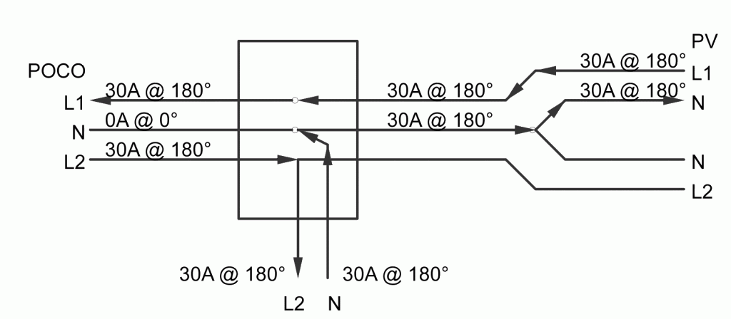
30A of unbalanced generation on L1 going through the neutral plus 30A of unbalanced load on L2 going in the same direction through the neutral. Relative phase angle of 180 (L1 versus L2) + 180 (in versus out) degrees, so the currents in the neutral add.
One strong reason to use a 120/240 GTI with phase voltage monitoring instead of separate 120 GTIs.

So far as I can tell my pair of OutBacks will do the trick -- when there's a higher load on L2 than L1, the L1 inverter backs off and L2 picks up. L1 is the "master", so normally it starts first, then the L2 inverter is turned on when the output reaches 10 amps or so. But they "trade places" when the neutral gets imbalanced by more than 5 or 10 amps.

The microinverters could care less -- they output the same on L1 as L2. The batteries may not be long for this world ;)
 

GoldDigger

Moderator
Staff member
Location
Placerville, CA, USA
Occupation
Retired PV System Designer
[three-phase using single phase inverters]
??? Please explain what has not been thought through.

Just as for the 120/240 3-wire case, in a 3-phase 208Y/120 4 wire you can have a situation in which you have unbalanced load on one phase and unbalanced generation on either or both of the other phases leading to a neutral current higher than it would be even with the worst case of unbalanced load only.
PV feeding only one phase (L1 to N) at max L1 current will produce exactly the same current in N. When you add maximum load to L2-N and L3-N only, you add the vector difference of those two currents to the neutral in phase with the PV current.

If you insure that the PV current is balanced, or close to balanced, then the current it will add to the worst case neutral current going to (unbalanced) loads only will not drive the neutral current above the rated value of the circuit.
If the unbalanced excess PV and unbalanced excess load are on the same phase, then you are just fine, since they will cancel.

Looking at the direction of the neutral current in the 120/240 case, it may help you if you think of a GTI output on the same phase as an unbalanced load.
If the two currents are equal in magnitude, no net current will flow in either L1 or N. The two neutral currents are opposite in direction.
Now if you move just the GTI to the opposite line conductor (L2), the direction of its neutral current must reverse, and be in the same direction as that of the L1 load.
 

Smart $

Esteemed Member
Location
Ohio
I'm with Smart$, not seeing it either. Seems to me the neutral current should still go in opposite directions and balance each other out. I'll wait and hope he draws the diagram though, he's better at that. :D
All current angles referenced to POCO L1 voltage angle (or completely disregard and follow the arrows :)).
diagram.gif
 

GoldDigger

Moderator
Staff member
Location
Placerville, CA, USA
Occupation
Retired PV System Designer
Very handy picture, but to create the situation tallgirl originally suggested, you need to have the PV be in the form of two separate 120V inverters, one on L1 and one on L2, with the one on L2 turned off.
Now look at the neutral current.

As long as you use a single 120/240 3-wire or 240V with neutral monitoring GTI, you will not have a problem, just as your diagram shows.
 

Smart $

Esteemed Member
Location
Ohio
Very handy picture, but to create the situation tallgirl originally suggested, you need to have the PV be in the form of two separate 120V inverters, one on L1 and one on L2, with the one on L2 turned off.
Now look at the neutral current.

....
Okay...???

diagram2.gif
 

jaggedben

Senior Member
Location
Northern California
Occupation
Solar and Energy Storage Installer
But they don't go in opposite directions, that's the problem. When the phase angle is 180 degrees, "loads" cancel, so the neutral current is the value of L1 - L2. This is the pretty normal case. However, if L2 is a "negative load" (production), L1 - (- L2) is a bigger number.

Ok, I'm seeing it now. I didn't catch that the case involved all generation and no load on L1, and the opposite on L2.

...
PV feeding only one phase (L1 to N) at max L1 current will produce exactly the same current in N. When you add maximum load to L2-N and L3-N only, you add the vector difference of those two currents to the neutral in phase with the PV current.

Makes sense, but in your initial post you referred to line-line inverters, not line to line-to-neutral. I don't think there's a problem with line-line setups, do you agree?

FWIW, I'm not aware of any micro-inverters that could be set up L-N except Exceltech, (which has no market share I'm aware of). But there are apparently a lot of string inverters set up this way in 480/277 wye configurations.
 

GoldDigger

Moderator
Staff member
Location
Placerville, CA, USA
Occupation
Retired PV System Designer
Ok, I'm seyeing it now. I didn't catch that the case involved all generation and no load on L1, and the opposite on L2.


Makes sense, but in your initial post you referred to line-line inverters, not line to line-to-neutral. I don't think there's a problem with line-line setups, do you agree?

FWIW, I'm not aware of any micro-inverters that could be set up L-N except Exceltech, (which has no market share I'm aware of). But there are apparently a lot of string inverters set up this way in 480/277 wye configurations.

I think I only mentioned line-to-line for 3-phase. While tallgirl set the context to 120the V in a 120/240 system.
In 3-phase, either L-L or L-N can cause this problem. (L-L on one side of the triangle is equivalent to L-N on the opposite vertex.)
 
Last edited:

jaggedben

Senior Member
Location
Northern California
Occupation
Solar and Energy Storage Installer
I think I only mentioned line-to-line for 3-phase. While tallgirl set the context to 120the V in a 120/240 system.
In 3-phase, either L-L or L-N can cause this problem. (L-L on one side of the triangle is equivalent to L-N on the opposite vertex.)

To my knowledge L-L configured inverters don't put any current on the neutral. So I don't understand how this problem can arise with those inverters, single phase or 3-phase.
 

GoldDigger

Moderator
Staff member
Location
Placerville, CA, USA
Occupation
Retired PV System Designer
To my knowledge L-L configured inverters don't put any current on the neutral. So I don't understand how this problem can arise with those inverters, single phase or 3-phase.

Thanks for catching that. There is a problem, just not on the neutral.
At each vertex which has a load only on one side and a generation only on the other side will have more that the normal line current into/out of that pair of windings. As a result the line conductor will be overloaded (and I think one transformer winding may end up overloaded too. Especially in an open delta.
 

jaggedben

Senior Member
Location
Northern California
Occupation
Solar and Energy Storage Installer
Thanks for catching that. There is a problem, just not on the neutral.
At each vertex which has a load only on one side and a generation only on the other side will have more that the normal line current into/out of that pair of windings. As a result the line conductor will be overloaded (and I think one transformer winding may end up overloaded too. Especially in an open delta.

Well that, at least, (the red part), if not prohibited by the code, is unlikely to be designed that way, and partly discouraged by the code. 705.100, while vague, encourages installers to have balanced interconnections. In the case where there might not be, namely on a high-leg delta, if an installer connected only to the 240/120 phase, and loads on the other phases are likely to be 3-phase loads, so the 'load only on one side' is unlikely.

AFAIK you are correct about open deltas, but hopefully utilities will prevent this problem in the interconnection process.

But finally, to circle back around to the neutral issue, take a look at 705.95(A) (2011 code).
The problem that you and tallgirl have pointed out is accounted for and prohibited in the code. I happened upon it while looking for the rules on unbalanced connections in 705.100.
 

tallgirl

Senior Member
Location
Great White North
Occupation
Controls Systems firmware engineer
Ok, I'm seeing it now. I didn't catch that the case involved all generation and no load on L1, and the opposite on L2.


Makes sense, but in your initial post you referred to line-line inverters, not line to line-to-neutral. I don't think there's a problem with line-line setups, do you agree?

Correct -- not a problem with L-L configurations. In a L-L configuration, assuming maximum L-N loads for both L1-N and L2-N are equal to the maximum L1-L2 production, the maximum neutral current is equal to the maximum of the largest L1-N or L2-N load.

FWIW, I'm not aware of any micro-inverters that could be set up L-N except Exceltech, (which has no market share I'm aware of). But there are apparently a lot of string inverters set up this way in 480/277 wye configurations.

Every now and again I see another microinverter pop up that is configured for 120 VAC, line-to-neutral. I agree that ExelTech's microinverters seem to be a fizzle, but SMA made 120 VAC string inverters for a while (see the SB1800), and OutBack (and others) make 120 VAC grid-interactive inverters. This whole neutral imbalance issue isn't going away any time soon.
 

tallgirl

Senior Member
Location
Great White North
Occupation
Controls Systems firmware engineer
But finally, to circle back around to the neutral issue, take a look at 705.95(A) (2011 code).
The problem that you and tallgirl have pointed out is accounted for and prohibited in the code. I happened upon it while looking for the rules on unbalanced connections in 705.100.

I read the 2011 ROP (on account of my 2011 is at the office, and I'm not ...) and it appears to have missed this case as well. I need to go to the office to find out why a software change seems to have been undone and will take a read of the actual text when I get there, but I'm still not hopeful.

This problem seems limited to supply-side interconnections, where a 2-pole breaker is used to connect to a new panel which includes both load and generation. So long as the load is balanced (L-L -- say, an A/C compressor), there's no issue. It's only when there are L-N loads and L-N generation.

I brought this up a number of years ago, back when I was one of the few people here doing anything with Article 690, and there wasn't a concern. If you look at how this thread evolved, with the number of people saying "not a problem", I wouldn't be surprised if this scenario has been missed in the 2011.
 

ggunn

PE (Electrical), NABCEP certified
Location
Austin, TX, USA
Occupation
Electrical Engineer - Photovoltaic Systems
Well that, at least, (the red part), if not prohibited by the code, is unlikely to be designed that way, and partly discouraged by the code. 705.100, while vague, encourages installers to have balanced interconnections.
But 705.100 talks about unbalanced voltages, not current. Apart from small voltage differences from differing voltage drop in conductors in an unbalanced interconnection, why would unbalanced inverters cause unbalanced voltage?
 

jaggedben

Senior Member
Location
Northern California
Occupation
Solar and Energy Storage Installer
I read the 2011 ROP (on account of my 2011 is at the office, and I'm not ...) and it appears to have missed this case as well. I need to go to the office to find out why a software change seems to have been undone and will take a read of the actual text when I get there, but I'm still not hopeful.

This problem seems limited to supply-side interconnections, where a 2-pole breaker is used to connect to a new panel which includes both load and generation. So long as the load is balanced (L-L -- say, an A/C compressor), there's no issue. It's only when there are L-N loads and L-N generation.

I brought this up a number of years ago, back when I was one of the few people here doing anything with Article 690, and there wasn't a concern. If you look at how this thread evolved, with the number of people saying "not a problem", I wouldn't be surprised if this scenario has been missed in the 2011.

In 2008, and earlier, it was in 690.62 as well as 705.95.

I don't know why you think the problem is limited to supply side interconnections.
 

jaggedben

Senior Member
Location
Northern California
Occupation
Solar and Energy Storage Installer
But 705.100 talks about unbalanced voltages, not current. Apart from small voltage differences from differing voltage drop in conductors in an unbalanced interconnection, why would unbalanced inverters cause unbalanced voltage?

My point was that it seems to me that most integrators design balanced or nearly balanced 3-phase interconnections by default (high leg deltas notwithstanding), and 705.100 is one small thing that encourages this.
 

ggunn

PE (Electrical), NABCEP certified
Location
Austin, TX, USA
Occupation
Electrical Engineer - Photovoltaic Systems
My point was that it seems to me that most integrators design balanced or nearly balanced 3-phase interconnections by default (high leg deltas notwithstanding), and 705.100 is one small thing that encourages this.
I understand and mostly I design balanced interconnects, but my question was how 705.100 addresses the issue, seeing as how it only talks about voltage.
 

jaggedben

Senior Member
Location
Northern California
Occupation
Solar and Energy Storage Installer
I understand and mostly I design balanced interconnects, but my question was how 705.100 addresses the issue, seeing as how it only talks about voltage.

I just think it encourages balanced connections because then there will be no AHJ questions about whether 705.100 is an issue.
 

ggunn

PE (Electrical), NABCEP certified
Location
Austin, TX, USA
Occupation
Electrical Engineer - Photovoltaic Systems
I just think it encourages balanced connections because then there will be no AHJ questions about whether 705.100 is an issue.
I have had those questions on a couple of somewhat unbalanced systems (Sunny Boys in phase to neutral configuration where a multiple of three inverters was not possible); I answered them by saying the inverters match grid voltages so there is no significant voltage imbalance, and that satisfied them.
 

tallgirl

Senior Member
Location
Great White North
Occupation
Controls Systems firmware engineer
In 2008, and earlier, it was in 690.62 as well as 705.95.

I don't know why you think the problem is limited to supply side interconnections.

I don't -- but the second a load is added to a line-side tap, it's no longer a line-side tap, no?
 
Status
Not open for further replies.
Top