- Location
- Windsor, CO NEC: 2023
- Occupation
- Hospital Master Electrician
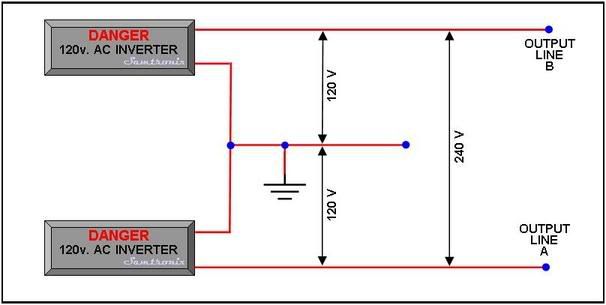
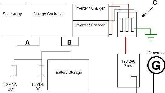
Can two 120V inverters be configured to supply 240V loads?
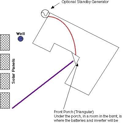
I'm working on a standalone 12VDC solar house, which has a 240VAC well pump. Fortunately, I am not dealing with the PV system, but the homeowner mentioned that something along those lines was going to transpire, and it aroused my curiousity. It sounds like it would be difficult to ensure that the inverters would be sync'ed to provide 240V.
This house has been a real treat: It's a post-and-beam structure with "SIP's" panels. Essentially styrofoam with channels in them to allow for wiring. Nothing like fishing every exterior wall on a new house!")
I'm working on a standalone 12VDC solar house, which has a 240VAC well pump. Fortunately, I am not dealing with the PV system, but the homeowner mentioned that something along those lines was going to transpire, and it aroused my curiousity. It sounds like it would be difficult to ensure that the inverters would be sync'ed to provide 240V.
This house has been a real treat: It's a post-and-beam structure with "SIP's" panels. Essentially styrofoam with channels in them to allow for wiring. Nothing like fishing every exterior wall on a new house!