rail orientation on steep roof

OK, so if your beam member is only subjected to uniform loads, I get that the support points should be (sqrt(2)-1)/2 of the way in from each end, which agrees with your statement that the distance between supports is 1/1.71 of the beam length.

But if you expand the allowable loading cases to any distributed loading up to some maximum limit over any subset of the beam, then to minimize the maximum moment the support points should be 1/4 of the way in. That way the moment at the support from just loading the cantilever (which moment will be independent of the loading on the rest of the beam) equals in magnitude the moment at the beam midpoint from just loading the central span (with no load on the cantilevers).

Or switching gears slightly, if the allowable loading cases consist of a single point load anywhere along the beam, then the optimal support location is 1/6 of the way in from the end. That way the maximum moment from the point load being at the end of the beam will be equal in magnitude to the maximum moment from the point load being at the midpoint of the beam.

Cheers, Wayne
When you leave the load distribution completely open-ended, there is no conclusive location for optimizing the support points. You need some definition of the load distribution as a starting point.

The quarter points would optimize strength, given a uniform load on any given segment, and no load on all the other segments, with segments defined by the ends and support points. This is unlikely in reality, because it'd require that the loading distribution abruptly drops from uniform to zero after crossing a support, when there's no causal reason why this would be the case.

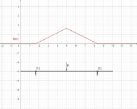
You are correct with your example of a point load at any variable location. An application of this, would be a load-bearing trolley that needs to glide along a rail of negligible weight, and one that can glide past the support points. Cantilevers of L/6, and a span of 2L/3, give the ideal locations that minimizes the worst case bending moment, which either occurs when the load is at the very beginning, or the very middle of the span. I made a Geogebra page, with a slider that allows you to see how the load position and support span affects the bending moment diagram. Adjust Xp to move the point load, and adjust s to modify the span.
 
When you leave the load distribution completely open-ended, there is no conclusive location for optimizing the support points. You need some definition of the load distribution as a starting point.
None of the 3 examples I discussed involved an open ended load distribution. Each example has a well defined allowable collection of load cases:

1) (Your original) Any uniform load omega on the entire beam, where omega may be between 0 and some fixed maximum omega_0. For this family, the maximum moment for any configuration clearly scales with omega, so it suffices to consider the single load distribution of the maximum load omega_0 to find the worst moment.
2) Any integrable pattern of distributed load on the beam, where the load density at any point never exceeds some fixed maximum omega_0. Now the worst case loading may differ between different support locations.
3) Any single point load P up to some maximum P_0 at any single point on the beam. Again the worst case moment clearly scales with P, so it suffices to consider P_0 only.

Then for any one of the above collections, you can define M(a,b) to be the supremum over all load cases of the maximum moment for each load case when the supports are at locations a and b. And then find the pair (a_0,b_0) that minimizes the function M; those are the optimal support points.

We're in agreement on optimal support points for collections 1 and 3 above. My claim is that for collection 2, the optimal support points are at the quarter points of the beam.

So say you are setting up a plank on some scaffolding, and the plank is supported at two points with holddowns. The workers may stack bricks along the plank in any possible pattern, but know not to stack them more than 5 high at any point. Where should you put the supports to allow the use of the lightest possible constant cross-section plank? At the quarter points.

Cheers, Wayne
 
Last edited:
Interestingly enough, my Geogebra file glitched, and made the following screenshot as I varied the point load position. It looks cool, and illustrates a lot more of the situation at once.
1728018455394.png
 
2) Any (say once differentiable) pattern of distributed load on the beam, where the load density at any point never exceeds some fixed maximum omega_0. Now the worst case loading may differ between different support locations.
We're in agreement on optimal support points for collections 1 and 3 above. My claim is that for collection 2, the optimal support points are at the quarter points of the beam.

So say you are setting up a plank on some scaffolding, and the plank is supported at two points with holddowns. The workers may stack bricks along the plank in any possible pattern, but know not to stack them more than 5 high at any point. Where should you put the supports to allow the use of the lightest possible constant cross-section plank? At the quarter points.

I can come up with two examples that fit this criteria that have significantly different solutions. Consider L=10 ft, for a nice round number.

Example 2A: a triangularly distributed load, starting at zero at x=0, and building up to a maximum load density at x=L.
Example 2B: a parabolically distributed load, with its peak load density at x=L/2, and zero load at x=0 and x=L.

These are both once-differentiable load density functions, with the same maximum load density, and a load density that always has the same sign. However, the optimal points to support them are different. Intuition would tell us that the supports should be symmetric in example 2B, and the supports should be biased to the right in example 2A, and this intuition would be correct.

I haven't explored exact solutions yet, but by trial & error, I got the following:
Example 2A: Support 1 at x=3.8 feet, and support 2 at x=8.6 ft. Span = 4.8 ft, w/ 3.8 ft left cantilever and 1.4 ft right cantilever
Example 2B: Support 1 at x=2.78 feet, and support 2 at x=7.22 ft. Span = 4.44 ft w/ symmetric 2.78' cantilevers.

The result for 2B surprised me that "closer than quarter points" was the solution, since my instincts are for uniform loads. Then again, I should expect that for a load distribution that's biased toward the center.

The bottom line is, distribution of the load governs the best distribution of supports. You'd have to look at most probable distributions of load, in your scenario of stacking bricks, to narrow down your search for a solution that optimizes the strength of the scaffold. Then again, scaffolds are usually supported at the outer ends anyway, to avoid a negative reaction load that would topple the board, or buckle the hanging cables.
 
I can come up with two examples that fit this criteria that have significantly different solutions.
No, you are posing a different problem than I posed as Example 2, by insisting on looking at only a fixed shape of the loading, rather than allowing the shape of the loading to vary.

Think about my brick formulation as the discrete version of my Example 2. Divide the plank up into a finite number of locations that bricks can go, and as I said we can stack them only up to a certain fixed height. That's a finite collection of possible loadings, but of many different shapes.

Now for any choice of support locations (a,b) and any of those loadings, we can calculate the maximum moment in the beam. So let the loading vary with the support locations fixed at (a,b), and find the maximum of those maximum moments. That's M(a,b). Now let the support locations vary and find the choice that minimizes M(a,b). That choice is the optimal place to put the supports. It minimizes the worst case maximum moment.

Cheers, Wayne
You are essentially asking, "how long is a piece of string?", the way you've stated your premise. This is like trying to find the area and centroid of an arbitrary shape that is 10 ft long and 2 ft wide, with no other information about what shape it is.

I gave you two examples of loading profiles that met your criteria, with significantly different solutions, and there are infinitely many more I could give. It's not possible to find an idealized support point location pair that is optimized for all of them.
 
You are essentially asking, "how long is a piece of string?",
No, you are still completely missing the point. Let me try phrasing it this way, in terms of the discrete version of the idea:

Let's say we have a bunch of identical planks that we know have identical bending moment capacity and failure behavior, and a bunch of identical bricks. Plus we have two supports that we can install anywhere along the plank, and the supports provide uplift resistance. The plank is just the right size to hold a single row of bricks along its length for some integer number of bricks, say N. We mark these brick locations on the plank.

With this equipment, we could play a game. You get to set up the plank with the supports anywhere you want. I then get to strategically add bricks to the plank until the plank fails in bending. I can only add bricks in the marked locations on the plank, or directly on top of a brick that's already there, so we have 0 to N different stacks on the plank at any point during the game. Your score is the height of the highest stack of bricks on the plank at the time of failure (excluding the brick causing the failure).

This is a well defined problem. There is a "best" location to put the supports that will maximize your score. Put the supports in a different location, and if I'm clever I can cause the plank to fail with a shorter maximum height stack of bricks, so your score is lower. [Up to the loss of detail in the discretization, but we could make the bricks really lightweight so the scores are high enough so we that can differentiate small effects.]

That's the discrete version of Example 2. In the discrete version of Example 1 (your original statement), I only get to add bricks in groups of size N, with one brick going onto each of the N different locations. And in the discrete version of Example 3, I have to pick a single location, and I can only add bricks to that one stack. Each of these games has its own optimal location for the supports.

This discretization is just for rhetorical purposes. We can do the same thing in the continuous case.

Cheers, Wayne
 
Last edited:
But if you expand the allowable loading cases to any distributed loading up to some maximum limit over any subset of the beam, then to minimize the maximum moment the support points should be 1/4 of the way in.
OK, the above is true, and here's a proof, more or less:

Let the length of the beam be 1 unit (adjust length unit as required). And let the limit on the distributed loading be 1 unit of weight per unit of length (adjust weight unit as required). So an allowable loading is given by some function L(x) on [0,1] where 0 <= L(x) <= 1. L better be sufficiently "nice," perhaps being integrable suffices.

We want to choose support points (a,b) so that the worst case moment at any section in the beam for any of the allowed loadings is minimized. This problem is symmetric about the beam midpoint, so it immediately follows that b = 1-a (the solution must be unchanged by the reflection x -> 1-x).

The shear V(x) and moment M(x) are linear in the loading pattern L(x). So we can divide up the interval [0,1] into a couple regions and consider L(x) as the sum of a couple different loadings, each one of which is zero outside one of the regions. Let's do that for the center span (a,1-a) and its complement.

[0,a] and [a,1] are the cantilevered beam segments. Any loading on just this region will give a moment M(x) that is everywhere nonpositive (hopefully I have the usual sign convention, but that doesn't matter). Conversely, [a, 1-a] is the central span, and any loading on just this region will give a moment M(x) that is everywhere nonnegative (definitely the opposite sign of the cantilever region).

So suppose some loading L(x) gives us our worst case value of M(x). We can write L(x) as L1(x) + L2(x), where L1(x) is zero on the span (a,1-a) and L2(x) is zero outside of (a, 1-a). We know M(x) = M1(x) + M2(x), where M1 and M2 are the moment distributions of L1 and L2. Then M(x) <= L2(x) as L1(x) is non-positive, while M(x) >= L1(x) as L2(x) is non-negative. Therefore if the worst case moment is positive, L2(x) will also be a worst case; while if the worst case moment is negative, L1(x) will also be a worst case.

In other words, we have shown that it suffices to consider the worst case moment from loadings that are either zero on (a,1-a) or zero outside that region. Furthermore, for such a loading, where it is non-zero, increasing the loading to the maximum value of 1 will only increase the moment magnitude |M(x)|. So we have reduced the problem to considering just two different loading distributions, L1(x) = 1 if x<a or x>1-a, 0 otherwise; and L2(x) = 1 if a <= x <= 1-a, 0 otherwise.

The maximum moment from L1(x) is -a2/2, while the maximum moment from L2(x) is (1-2a)2/8. So the optimal choice of a will minimize max(a2/2, (1-2a)2/8). This occurs when a2/2 = (1-2a)2/8. And the solution to that equation is a = 1/4.

Cheers, Wayne
 
Now, rail orientation on a steep roof...

Remember rail orientation on a steep roof?

This is a thread about rail orientation on a steep roof.

Apologies to Arlo Guthrie. :D
 
Top