
shortcircuit2
Senior Member
- Location
- South of Bawstin
The SMA back up power outlets require manual operation to turn on anyway, so it's not inconceivable to have a Rapid Shutdown device that can still operate on loss of AC, but has a manual override of some sort. FWIW, SMA has a Rapid Shutdown product that does not operate on loss of AC power. But it has a controller component which seems like it could be easily re-engineered to trigger on such loss and also function manually.
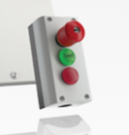
Interesting design on this product jb...
Here is a cut and paste from the instructions on how it operates...
4.1 Rapid Shutdown System
The Rapid Shutdown System consists of one or more Rapid Shutdown Boxes and one Rapid Shutdown Controller. PV systems equipped with the Rapid Shutdown System satisfy the requirements of the National Electrical Code® 2014 (Section 690.12). The Rapid Shutdown Controller activates and deactivates the Rapid Shutdown System and signals the status of the Rapid Shutdown System via the green and red LEDs. The Rapid Shutdown Box electrically discharges the PV generator conductors from the Rapid Shutdown Box to the inverter within ten seconds of activation of the emergency switch on the Rapid Shutdown Controller to ≤30 V. When the irradiation on the PV array is sufficient and the voltages have been electrically discharged in accordance with specification, the green LED on the Rapid Shutdown Controller glows green constantly. When none of the LEDs of the Rapid Shutdown Controllers are glowing after actuating the emergency switch, either the irradiation on the PV array is too low and, thus, the supply voltage of the Rapid Shutdown System insufficient or the installation of the Rapid Shutdown System is faulty or the Rapid Shutdown Box is defective.
Couple of comments...
1. It won't comply with the 2017 Code because it has no OFF indicator. (but it does have the visual indicator!)
2. It operates on DC voltage from the array. So the rapid shutdown function is inactive during darkness as is the PV Array. If there is a fire on a structure at night...and the Fire Department sets up flood lights to combat the fire, will the lights activate the array to a dangerous voltage?
 .....not sure why....maybe b/c I just got my first building permit plan-set rejected for lack of RSS:weeping::weeping:. Ahhh 2017.