Recept Feed

Status
Not open for further replies.

Alwayslearningelec

Senior Member
Location
NJ
Occupation
Estimator
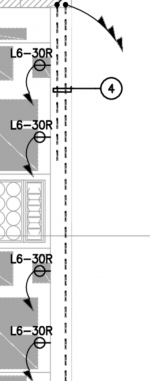
Engineer note is saying to feed these receptacles via mill work. So they’d require #10’s.

If fed with flex or hard pipe and daisy chaining would there be an issue with box fill and pulling #10’s through the receptacle boxes? They are separate circuits.

Not sure that’ how it should be done.
 

Attachments

  • Capture.PNG
    Capture.PNG
    149.9 KB · Views: 26
I think its an RFI issue. I believe the note was copied from other CAD note's. I don't know many situations where mill work
(wood-toe kicks, chair rail or even crown ((ceiling)) molding is used in this setting.

I would use a deep metal box with a box extension because the NEMA fitting will take up the a lot of the even a single deep metal box,
and yes it'll still be crowded. I also suggest you might consider combine pairs of circuits for pairs of receptacles.
Other than that run individual circuits with deep boxes and an extension ring &/mud ring.
 
Look on an A page for this cabinet.
Some cabinets are now being done with a chase to which the raceway can be ran. They have a removal back which gains you access.
I do not see an issue running multiple circuits through one raceway if you watch fill for both raceway ( 348.22) and outlet ( box fill artical 314). If you flex just go to that section of the code. You could also use MC #10.
Nice thing with flex ( FMC artical 348) would be one ground ( EGC).
We usually stub in hard pipe then use FMC as allowed or mc from first outlet.
Be sure to read 348.30 A and B
FYI: for others .30 would be securing and supporting in chapter 3 for raceways/ cable types.Test short cut. Go to raceway type and look at .30
Fun fact look for .30 in artical 340. Don't tell the insp.
This a test related question.
Be sure to read 340.10 (4)
 
This is the section of the cabinet. Look void in the back where receptacle box will be.
 

Attachments

  • Capture.PNG
    Capture.PNG
    257 KB · Views: 9
This is still an RFI issue IMO. I or no one else can answer this here!

I don't have a problem with what Tulsa E. presented, and this probably will be your install.
I've run circuits in the building wall for open face shelving.
I've run circuits like T. E. stated which had shelving installed with movable
interior back panel to hide power and telco. This was not implied here.

My belief is that you will have to figure out how to transition from multiply circuit to the run
down the cabinets.

I've never installed anything in a cabinet with a cabinet door on it.

I have real problems with this, you show the plan where it looks like a gap
then you present a cabinet elevation with no wall reference.

I'll bet ya a lunch that there will be a vertical mid stiffener
where you think your void is.

You need to get with someone with the answers, like why is an engineer doing
cabinet drawings. (joke)
 
Status
Not open for further replies.
Top