Residential Pole-Mounted Utility Transformer Grounding

Status
Not open for further replies.

dinos

Member
I am trying to help someone find out why the have significant 'net current' on the main service conductors feeding their home, and find a way to fix the problem.

The home is fed with (2) phase conductors and (1) neutral conductor (120/240V, 1ph/3w).

In the Main Panel, there are (2) bare conductors terminated at the neutral bus, with one of these conductors going through the garage slab (presumably to a ground rod) and the 2nd going to his basement cold water pipe. Near as I can tell, this ties in with grounding per NEC 250-50.

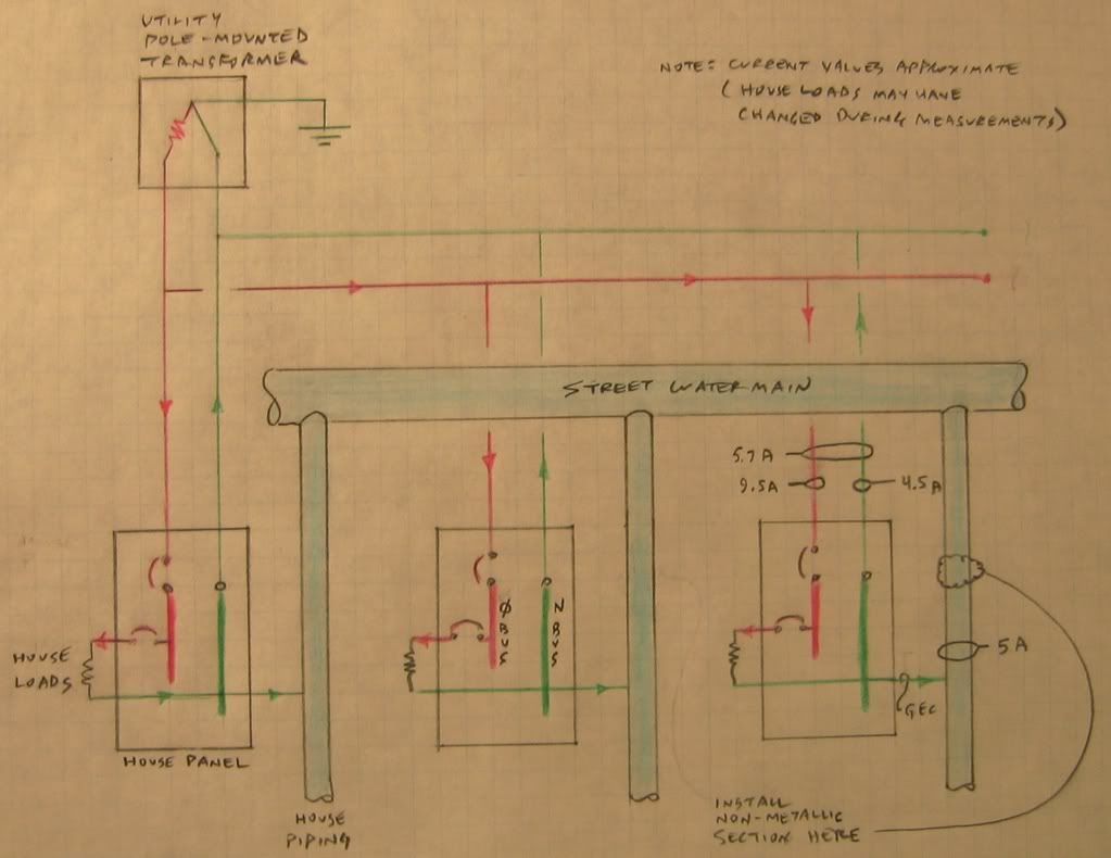
I measured the 'net current' on the main panel conductors (both incoming main phase conductors and the main neutral conductor in the current probe) and it was 5.7A (the phases individually were 6.2A and 14.1A, and the neutral by itself was 4.5A). With just the (2) panel main phase conductors in the current probe, the measurement was 9.5A - technically this is the current I should see on the main neutral conductor, but again, the incoming neutral conductor current was only 4.5A.

In the basement, I clamped on the cold water pipe between the ground conductor connection point and where the pipe exited the slab and measured approx 6.8A. I'm thinking this reflects the approx 5A 'missing' from the main neutral conductor (the house loads might have changed somewhat between readings).

We opened all of the panel branch circuit breakers, and we were left with about 1A of net current on the panel main conductors (I did not measure the cold water pipe again). I realize this could be ground current coming from other homes with their own grounding issues, but that is not the focus of this question.

We put the breakers back on one at a time to see how each contributed to the 'net current' problem, and almost without exception, each one contributed something to the net current. I find it hard to accept that every circuit in the house had an improperly grounded neutral or other grounding problem so for the moment am concentrating on grounding sources external to the house.

My question is, does anyone have ideas of how pole-mounted utility transformers serving residential areas are grounded? Is it possible that they are grounded directly to the street water main? The reason I ask is that it seems like the panel neutral current is dividing fairly evenly between the panel neutral conductor which is the preferred path back to the utility transformer, and the cold water pipe which is not a desirable path at all! I'm guessing that they are dividing evenly because the cold water pipe path may be of low resistance (just like the panel neutral conductor path) because it connects with the street main and the street main might be intentionally connected to the utility transformer to provide grounding for the transformer.

Someone suggested that the home owner should install a 'plastic' (non-metallic) section of pipe in the cold water piping between his home and the street main (as long as it is 10 feet or more from the house) thereby removing the 2nd low resistance path, with all of the neutral current now returning to the utility transformer via the panel main neutral conductor as it is supposed to.

Does anyone have opinions/advice about this possible solution?

I wish I could include a sketch with this post to make it easier to understand the electrical layout...
 
Without actually witnessing your procedures of measurement and knowing what type of tester used, I will make a few general statements to help you.

The utility company grounds their system both on the primary side and secondary side of the transformer. There is a good chance that you are seeing some of their current on the cold water pipe.

As you said, you would be surprised if there were so many neutral to ground bonds in the house...I would not be.


There may be other neutral issues that you are unaware of. It would be fun to come and see this house, but I doubt that will happen.

I would suggest getting a good/experienced electrician there to help, sometimes their experience in the field will find what you may be missing.
 
Pierre C Belarge said:
Without actually witnessing your procedures of measurement and knowing what type of tester used
I measured the 'net current' on the main panel conductors (both incoming main phase conductors and the main neutral conductor in the current probe)
The current probe was a Fluke 33 true RMS ammeter.

Pierre C Belarge said:
The utility company grounds their system both on the primary side and secondary side of the transformer. There is a good chance that you are seeing some of their current on the cold water pipe.
Do you know specifically how the secondary of the transformer is grounded?is it via a ground rod, connection to the street water main, etc.
We opened all of the panel branch circuit breakers, and were left with about 1A of net current on the panel main conductors
With all of the house loads off, this can only be current from an external source i.e. other neighboring homes with their own ground current problems.

Pierre C Belarge said:
As you said, you would be surprised if there were so many neutral to ground bonds in the house...I would not be.
Agreed, though I would expect that most of the return current from improper ?neutral to ground bonds in the house? would still ultimately make its way back to the main panel, and from there it should return to the utility transformer via the main panel neutral, not approx 1/2 via the neutral and approx 1/2 via the cold water pipe?unless the cold water pipe was providing a low resistance path (comparable to the main neutral conductor path) which is why I am asking about the possibility of a direct connection between the utility transformer and the street main.

Pierre C Belarge said:
I would suggest getting a good/experienced electrician there to help, sometimes their experience in the field will find what you may be missing.
The homeowners brother is an experienced Local 3 electrician and has offered his input to the matter. I have been in electrical consulting for 20+ years. The homeowner was successful in finding an expert in electromagnetic field (EMF) consulting who provided input on the net current issue, specifically as it relates to the cold water pipe and the installation of an 'non-metallic section' into it.

My questions are:
...does anyone have ideas (specifically) of how pole-mounted utility transformers serving residential areas are grounded?
...is it ok to install a 'plastic' (non-metallic) section of pipe in the cold water piping between his home and the street main (as long as it is 10 feet or more from the house)
 
dinos said:
...does anyone have ideas (specifically) of how pole-mounted utility transformers serving residential areas are grounded?
The primary and secondary neutral is jumpered, and the grounding conductor is run down the pole to a rod or butt coil at the base of the pole. Most utilities will do this at each and every span.
 
mdshunk said:
The primary and secondary neutral is jumpered, and the grounding conductor is run down the pole to a rod or butt coil at the base of the pole. Most utilities will do this at each and every span.

I agree with mdshunk, I would check the pole for missing conductor to rod. In this area most seem to be missing. Copper theives, gotta love them.

Tom
 
It may not be this house.
If the area has metallic water service lines, and a house next door has a open neutral, its neutral current can be coming in on this ones water pipe and then to the neutral.
A study done by the american water works association on grounding/pipe corrosion recommended installing a 12" length of NM pipe at least 10 feet from the building.
About one water meter reader is shocked daily in the US due to current on water pipes
 
mdshunk said:
The primary and secondary neutral is jumpered, and the grounding conductor is run down the pole to a rod or butt coil at the base of the pole.
That's good information. Thanks.
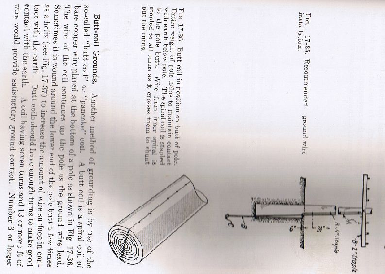
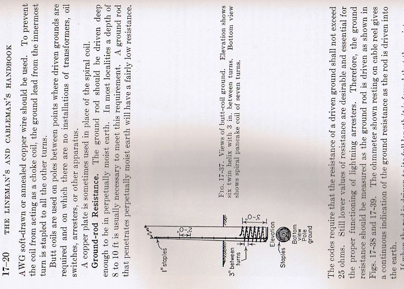
All I could find on the internet about "butt coils" was "A butt coil is a spiral coil of bare copper wire placed at the bottom of a pole"...is there another term for this component that anyone knows of?
 
Dinos, there is nothing sophisticated about "butt coils". A piece of solid copper attached to the primary neutral is run down the pole and stapled periodically, at the bottom of the pole it is simply wrapped around the base, this assures that it is in contact with the earth, this then becomes part of the utility's MGN (Multi Grounded Neutral) system.

This solid conductor is attached to the pole before it is set.


Roger
 
roger said:
..."butt coils". A piece of solid copper attached to the primary neutral is run down the pole and stapled periodically, at the bottom of the pole it is simply wrapped around the base, this assures that it is in contact with the earth, this then becomes part of the utility's MGN (Multi Grounded Neutral) system. This solid conductor is attached to the pole before it is set.
Thanks for the excellent description...I can picture it very well now.
 
Butt coils have fallen out of favor, and rod electrodes are generally being used instead. Butt coil:

polebutt1.jpg

polebutt2.jpg
 
If there is a common metal underground water piping system this issue of "net current" will exist even where there are no neutral grounding problems or code violations. The metal underground water pipe is connected in parallel with the grounded conductor because the code requires the metal underground water pipe to be used as a grounding electrode. It is not uncommon to find 25% or more of the grounded conductor current flowing on the water pipe. This current comes from both the service in the building and all of the other services that are connected to the metal underground water piping system. You can install the non-metallic section of water pipe at any point outside of the house. If it is closer than 10' to the building, then you don't have to use the water pipe as a grounding electrode, but the interior metal water piping system still must be bonded per 250.102.
Don
 
don_resqcapt19 said:
If there is a common metal underground water piping system this issue of "net current" will exist even where there are no neutral grounding problems or code violations. The metal underground water pipe is connected in parallel with the grounded conductor because the code requires the metal underground water pipe to be used as a grounding electrode. It is not uncommon to find 25% or more of the grounded conductor current flowing on the water pipe. This current comes from both the service in the building and all of the other services that are connected to the metal underground water piping system. You can install the non-metallic section of water pipe at any point outside of the house. If it is closer than 10' to the building, then you don't have to use the water pipe as a grounding electrode, but the interior metal water piping system still must be bonded per 250.102.
Don
Excellent answer!
I've made an attempt to sketch this scenario and post it...this could be exactly what is going on at the man's house I mentioned.
sketchfullsize.jpg
 
Last edited:
Utility grounding electrodes

Utility grounding electrodes

As to your question of how pole-mounted utility tx's are grounded. In my state (Va) we use ground rod electrodes. The standard is set at 25 ohms or less in distribution, so we megger and add rods to achieve this standard. This standard is applied at every pole with an inductive or capacitive device attached (also switches). Other poles you may see, such as street light, disconnect, fused or just wire support poles, there are just one non meggered 6 ft cu clad ground electrode.
The electric utility does not attach to city water mains. The utility grounding system is self sufficient.The grounding system of a distribution system is governed such that it is an efficient, effective means of protecting equipment and the general public from hazardous conditions. I suggest you call your local utility and have the grounds checked from the tx pole to the customers line side meter base connection.
You have an open or deteriorating neutral. The current shift is a symptom of an incoming neutral problem. If you check your voltage you will see a shift from one leg to the other, as you know volt and I are inversely proportional.
I did not mean to make a short story long, but I felt a need to get involved on this one..............
 
Last edited:
Finally, note that making the water pipe non-metallic instead of metal is just going to move the problem. You need to ground your house, so you'll probably have rods or something else. Your ground electrode is a parallel path back to the utility. All transformer secondaries are bonded to the common lower wire between power poles, so every ground rod in the neighborhood is a path back to your transformer (and vice-versa).

Your ground rods will conduct a little bit of the current from your neighbors back to the transformer (regardless of whether they share your transformer or have a separate one down the street). Take a careful look at the transformers in your neighborhood (if it is overhead). I think you'll find the bare neutral from your house is connected to the bottom wire strung across the utility poles. The neutral of each transformer connects to this same wire. Plus, the utility has their own ground electrode from most poles.

I suspect the current flowing on the grounding system will be much lower if you only have rods as opposed to nice long metal water pipes, but you can't make it go away. It will be worse if your neighbors have long cable runs to their house, undersized neutrals, or a corroding/failing neutral (all cause a higher voltage drop across their neutral which increases the amount of current flowing in the earth).

You may want to read here for more info: http://emfrelief.com/stray.htm
 
ServiceTech,
Who sets this 25 ohm standard for your utility? I have never seen multiple grounding electrodes used by any utility in my area. There really is no need for any individual electrode in the utiltiy system to meet a standard like that, as all of the electrodes in the system, both on the utiltiy side (primary and secondary) and the customer side, are connected together creating a very large low impedance grounding electode system.
However, the better the grounding electrode system is at each end of a service drop, the larger the percentage of the grounded conductor current flowing outside of the grounded conductor will be. The "net" current increases as the impedacne of the grounding electrode systems goes down.
Don
 
Effective grounding

Effective grounding

Hi Don,
In the electric utility industry our standards are set by the NESC http://standards.ieee.org/nesc/. As the NESC is used as a guideline for our standards the utilities can add upon those guidelines, but CANNOT degrade them. With that in mind, the company I work for (Dominion, http://dom.com) established that in substations the ground resistance (which as we all know changes sometimes dramatically in short periods of time) MUST be meggered at 10 ohms or less, and I might mention the ground scheme is nothing short of impressive (and expensive !!). In distribution the ground resistance MUST be meggered at 25 ohms or less.
Due to the nature, and the design of our distribution system we must and strive to keep a low impedance on the system. When a problem occurs on the utility system neutral (ground) we (the customer) do see the results of such a failure. That is one reason I stress the importance of the customer side ground. IMO the customer side grounding is a backup to the utility system in case of failure.
I have resolved issues with several customers involved, where our system neutral has failed. Of those several (maybe 10) customers, only one had a severe enough problem to call us. The other nine were not so concerned. I talked to eight out of the ten and they all reported the same isuues, but were not severe enough to be concerned or they stated they were going to call an electrician later if it continued. Investigating the issue further, I found an Inadequate panel ground in the customers home whom complained. Because of that inadequate ground in the cust. panel they saw the worst of the effectcs of our ground failure.

You are right Don , the net current will increase as the impedance of the ground system goes down, thus my point of an effective and efficient ground system. It is a well established grounding system most utlities employ.
 
Last edited:
Servicetech, welcome to the forum.

Even though this is an NEC site many of us are aware of the NESC as well.

You have come to the right place if you want to take about grounding issues.:cool:

You may get a little beat up about many utilities use of grounding electrodes for ground fault / personal protection of circuits operating at less than 300 volts to ground as many utilities do at street light poles. ;)
 
Thank you iwie,
I've been beat up by the best, and I know from reading you , you are one of the best. I've been taught, all poodles are dogs, but not all dogs are poodles!!
Could you expand on your statement about personal protection on circuits 300 volts or less.
What does the NEC say about ground electrodes, does it list any attributes? In my area the AHJ says a 3 ft electrode below the service panel, no megger is required.
 
Last edited:
Status
Not open for further replies.
Top