RV Voltage Drop

Status
Not open for further replies.

jmshiller

Member
Location
Marco Island
I have to design an RV park w/ 50 amp pedestals, the loads are simple enough per art. 551 and will be fed w/ a 200 amp feeder. The question is about the voltage drop. (7) 50 amp pedestals, longest run is 280 feet. This is in Florida and the Energy code requires a maximum 2% VD. Is the I in the (2 K I L) 200 amps or 50 amps? I would expect the full feeder load but need help?
 

kwired

Electron manager
Location
NE Nebraska
I have to design an RV park w/ 50 amp pedestals, the loads are simple enough per art. 551 and will be fed w/ a 200 amp feeder. The question is about the voltage drop. (7) 50 amp pedestals, longest run is 280 feet. This is in Florida and the Energy code requires a maximum 2% VD. Is the I in the (2 K I L) 200 amps or 50 amps? I would expect the full feeder load but need help?
Keep in mind that the amps you see at the feeder breaker is not the same amps you will see at the furthest pedestal, but if running 200 amp conductor all the way to the last pedestal you start to correct voltage drop before even calculating for voltage drop.

I did not look at what load calculation requirements are but obviously if you can put 7 50 amp receptacles on a 200 amp supply - there is some allowable factoring in the section covering this. So for simplicity lets say we have one seventh of 200 amps for load at each pedestal, about 28.5 amps, if the first pedestal is only 25 feet from the source you already dropped the load by 28.5 amps between the first and second pedestal, and will drop it by 28.5 again at the second pedestal. The last segment of feeder is only loaded to 28.5 but is a 200 amp conductor.

Also remember that actual voltage drop is not so much dependent on estimated load calculations or demand factors but is directly related to actual current and conductor size/length.
 
Last edited:

petersonra

Senior Member
Location
Northern illinois
Occupation
engineer
I have to design an RV park w/ 50 amp pedestals, the loads are simple enough per art. 551 and will be fed w/ a 200 amp feeder. The question is about the voltage drop. (7) 50 amp pedestals, longest run is 280 feet. This is in Florida and the Energy code requires a maximum 2% VD. Is the I in the (2 K I L) 200 amps or 50 amps? I would expect the full feeder load but need help?

Are you tapping the pedestals off of a single set of conductors?

If so, keep in mind that the current will be less the farther you go.

My guess is that there is some accepted way to make this calculation.
 

jmshiller

Member
Location
Marco Island
RV Voltage Drop

As to the actual design, I haven't done that yet. The load is based upon Table 551-73. 7-9 @55%. 7*9600= 36960VA / 240 = 154 amps. I need to do the voltage drop calculation. At 50 amps (each Pedestal) I am OK, but if I have to do the loaded feeder it gets to be a problem. I am not able to install the feeder in the middle, only on one end. Appreciate the input, look forward to solving this.
 

rlundsrud

Senior Member
Location
chicago, il, USA
Southwire has a free app that is very nice for calculating voltage drop. I would do each individual pedestal calculation individually and size the pedestal conductors accordingly. As far as sizing the 200 amp service I would add up the individual loads and base my calculation on the relative length of the 200 amp cables.
 

kwired

Electron manager
Location
NE Nebraska
As to the actual design, I haven't done that yet. The load is based upon Table 551-73. 7-9 @55%. 7*9600= 36960VA / 240 = 154 amps. I need to do the voltage drop calculation. At 50 amps (each Pedestal) I am OK, but if I have to do the loaded feeder it gets to be a problem. I am not able to install the feeder in the middle, only on one end. Appreciate the input, look forward to solving this.
One problem is the load is not clearly defined. Your load calculation is total load with demand factors based on 7-9 units, does not tell us what load is per unit, only that demand factors should allow for enough ampacity for the entire feeder supplying 7-9 units in most instances. Actual voltage drop will depend on actual load - which you know will vary, so design to what you think may be worst case - there is no NEC requirement for this. Otherwise once you determine a worst case load per unit or at a particular unit, you about need to calculate by point to point. Find the drop from source to first unit. Calculate drop again for worst case current that may be on conductors between first and second unit and base the voltage available at second unit, but remember worst case the supply on this segment is less then at the source - you need to subtract the VD in the first segment from supply as well as second segment to come up with actual voltage at second unit. - VD will be less at each segment as you lose load after each segment - you likely find the last few segments , maybe even up to last 2/3 or 3/4 of the run don't even need to be 200 amp conductors as far as VD is concerned, but they still need to be 200 amp conductors if protected by 200 amp overcurrent device.
 

jmshiller

Member
Location
Marco Island
RV Voltage Drop

As far as the known load, can't say, RV park and that's why I used the demand in 551-73. The Energy code in Florida requires a max of 2% VD on feeders. I am now leaning to segmented as suggested by 2 post. But still have to determine the proper load in amps? Appreciate the input and hope to find a reasonable solution.
 

kwired

Electron manager
Location
NE Nebraska
As far as the known load, can't say, RV park and that's why I used the demand in 551-73. The Energy code in Florida requires a max of 2% VD on feeders. I am now leaning to segmented as suggested by 2 post. But still have to determine the proper load in amps? Appreciate the input and hope to find a reasonable solution.
Maybe you need to ask Fl how to determine this unknown load then. If they are ones requiring it, they need to either tell you how to do it or at least provide references where you can learn how to do it.

Do they measure VD? Seems you would easily pass if there were little or no load when they made measurements.

Without doing any calculations I am fairly confident you come up with fairly decent voltage drop results as long as it is not a long run to first pedestal just with 4/0 alum or 3/0 copper, but not sure if you can guarantee as low as 2% at first pedestal or two if they are not pretty close to source. Kind of assuming there is fairly equal spacing between pedestals.
 

Phil Corso

Senior Member
JMShiller,

You may be able to use the EXCEL Sheet I provided earlier. It covers multiple, equally-spaced, single-phase or 3-phase, unity or non-unity PF, loads! For a free-copy, contact me off-forum!

Regards, Phil Corso, equall
 

Smart $

Esteemed Member
Location
Ohio
Maybe you need to ask Fl how to determine this unknown load then. If they are ones requiring it, they need to either tell you how to do it or at least provide references where you can learn how to do it.

Do they measure VD? Seems you would easily pass if there were little or no load when they made measurements.

Without doing any calculations I am fairly confident you come up with fairly decent voltage drop results as long as it is not a long run to first pedestal just with 4/0 alum or 3/0 copper, but not sure if you can guarantee as low as 2% at first pedestal or two if they are not pretty close to source. Kind of assuming there is fairly equal spacing between pedestals.
Code minimum per 50A pedestal is 9600VA for either a 120/240 or 120/208 supply. That's 40A and 46A respectively. Seems reasonable to use these values for a segmented voltage drop calculation unless FL has some stipulated method which contradicts using these values. There will likely never be known loads for a true calculation.

Ampacity of any segment but the last cannot be less than considered protected by the feeder OCPD. The last segment can be a lesser ampacity [240.21(B)(5) tap rule]. Assuming a 120/240 supply, 9600/240*7*55%=154A as noted by OP'er. Minimum feeder OCPD is 175A per 240.6. Using a 200A OCPD increases the minimum ampacity of all but last last segment... but is better suited for potential heavy loading.

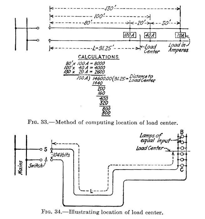
I believe the widest accepted method for calculating segmented voltage drop on a single size run is the load center method.
voltdropmultiloads.jpg
 

Smart $

Esteemed Member
Location
Ohio
...

I believe the widest accepted method for calculating segmented voltage drop on a single size run is the load center method.
...
Where using a tap for last segment calculate that segment separately. Do not include that segment in the load center calcualtion, but use the load sum for last load. For example, say there are seven segments each at 50' from preceding, each at 40A. Calculate as:

1 50ft?40A=2,000
2 100ft?40A=4,000
3 150ft?40A=6,000
4 200ft?40A=8,000
5 250ft?40A=10,000
6 300ft?80A=24,000
...........280A) 54,000 = 192.9ft, distance to load center
 

Smart $

Esteemed Member
Location
Ohio
... Seems reasonable to use these values for a segmented voltage drop calculation unless FL has some stipulated method which contradicts using these values. There will likely never be known loads for a true calculation.

.... Assuming a 120/240 supply, 9600/240*7*55%=154A as noted by OP'er. ...
Also seems reasonable to use 154A in conjunction with the calculated load center distance for voltage drop calculation. :D
 

jmshiller

Member
Location
Marco Island
RV Voltage Drop

Appreciate the many comments, here's the design I plan on. 400 amp 120/240 1 ph meter, (2) 200 map main breakers (2) feeders, initially 250 MCM AL, direct buried with a loop feed for 7 50 amp metered pedestals. Applying the demand in Art 551-73 (7-9) pedestals = 55% demand, 9600 * 7 = 67200 VA * .55 = 36960 / 240 = 154 amps. Longest run w/ loop is approx. 300 feet. Florida energy code limits VD to 2%. Seems that a segmented VD is whats needed, I also have to show formula on permit set. The pedestals have 350 MCM lugs for the loop feed. The park is existing as is distribution, I can't design the distribution in the center, has to come from one end, hence the long runs.
 

jmshiller

Member
Location
Marco Island
RV Voltage Drop

JMShiller,

You may be able to use the EXCEL Sheet I provided earlier. It covers multiple, equally-spaced, single-phase or 3-phase, unity or non-unity PF, loads! For a free-copy, contact me off-forum!

Regards, Phil Corso, equall

Phil, I appreciate your comments and yes if your spreadsheet is available I sure could use it. I am an EC in Naples and this is my 1st park.
Thanks
Jim Shiller
jim@gulfsideelectric.com
 

kwired

Electron manager
Location
NE Nebraska
I have no idea what you are talking about... :?
I think he is saying if it is three phase vs single phase and you balance the loads across the phases you have less current per phase conductor.

I still think 551.40 does not allow use of a 208/120 volt system. It says a system rated 120 volts - two wire, or a system rated 120/240 - three wire. The place it says 208(-230) is where it is referring to rating of connected equipment, not the supply system. Can't say I know why they don't want a 208/120 supply but I think that is the intention.

551.40 120-Volt or 120/240-Volt, Nominal, Systems.
(A) General Requirements.
The electrical equipment and material of recreational vehicles indicated for connection to a wiring system rated 120 volts, nominal, 2-wire with equipment grounding conductor, or a wiring system rated 120/240 volts, nominal, 3-wire with equipment grounding conductor, shall be listed and installed in accordance with the requirements of Parts I, II, III, IV, and V of this article. Electrical equipment connected line-to-line shall have a voltage rating of 208?230 volts.
 
Status
Not open for further replies.
Top