SEW EURO DRIVE 12 Lead Motor

Merry Christmas

Saturn_Europa

Senior Member
Location
Fishing Industry
Occupation
Electrician Limited License NC, QMED Electrician
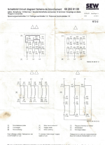
I am wiring up a 10 hp 3 phase motor to 480v. Its an IEC 12 lead motor. The data sheet is attached. There are two sets of each: RED BLACK BLUE wires and WHITE BROWN YELLOW wires. For a total of 12 wires. None of the wires are labeled.

The wiring options are Delta and Double Delta.

Which wiring option is for High Voltage?
 

Attachments

  • SEW EURO DRIVE .png
    SEW EURO DRIVE .png
    439.1 KB · Views: 17
I could not read the markings in the upper drawing but you might want to first talk to your motor repair company that might ask you to drop this motor off for them to figure out. At my first job we only had 240 volts three power for motors ( fractional to 200 HP ). When we had motors rewound we had the motor rewind shop connect every motor for 240 volts and only bring three leads into pecker heads.
 
The single delta connection that @Joethemechanic highlighted is the high voltage connection.

The problem is that the 'datasheet' doesn't tell you the wire colors; it only gives terminal numbers. All of the wiring diagrams that I can find point to numbers on terminal blocks, not color coded wire leads.
 
1765327815850.png


The motor was stored in a wooden box that was too small for the motor termination box to fit in. So they pulled the termination box and the copper studs that the ring terminals land on. I found another spare that still had motor terminal box on it and I am pretty sure I have it wired correctly now. The problem is the wires are not labelled at all. It took a bit of guess work. But I think its wired correctly now.
 
Just a guess, two of each color is possibly same color for each end of one winding coil? Can verify that with continuity checks I guess.

Still need to figure out correct polarity and which coils need to be in series with one another.

Easier yet would be if the colors are for identifying polarity, say black red blue were one end of two of three individual coils, and brown yellow white were other end you could apply 240 volts to just one set and run the motor (no load on the shaft) and check to see if it runs with equal currents and verify rotation. Chances are if that works you have one of the two delta's figured out and you should be able to connect the other set parallel to it in the same configuration which is how both deltas need connected for 240 volts. Then you just need keep track of the sets and connect them in series instead of parallel. If you get wrong polarity on just one of the six windings it probably runs but will have counter torque on the one coil that has reversed polarity and a current imbalance because of it. Once you get it to where it runs with balanced current it should be connected correctly.
 
It's kind of embarrising. I've replaced and rebuilt lots of their gear motors, new bearings, seals, combining parts from the old ones, along with a new one to get the configuration I need in a pinch. But damned if I can remember wire colors. I even remember 380 volt wye connections. They are very popular motors in automated food production.

One think I can tell you for sure is, those insulated ring terminals are not factory. Somebody was into that motor
 
Top