Simple GFI tester question

Status
Not open for further replies.
Maybe I should start doing that? ;)

Sure! Let me know how that works.

Here's another one:

Start requiring the use of PVC benders 'identified for the purpose' when making field bends. 352.24

A conduit heater is just that, a heater. It is not making bends, nor is it designed to. The actual field bends are made (usually) with a person's hands, which is not 'equipment identified for the purpose'.

It's not your fault there is no such piece of equipment, that's just the way the code is written. :p

If, however, we try to rationalize the above, consider EMT. Would bending it by hand (or foot) be considered 'using equipment identified for the purpose'? No, of course not, but ironically we can, as no such requirement exists for EMT. As long as the tubing is not damaged, blah, blah, blah, you can bend it with anything! 358.24
 
For clarification:

This is a large home (Custom McMansion style house) built in 1995, EGCs were present and spliced properly. The only GFI I could find on the second floor was in the master bath and looked original to the date of the house. The other four baths were evidently on the load side of the GFI, but weren't tripping it using my Greenlee GFI tester, nor did they trip when the home inspector used whatever GFI tester he had. The other receptacles in the master bath also failed to trip the GFI using the tester (no more than a 20' run from the GFI recept.). There were also two powder rooms on the 1st floor that failed a GFI test, but I suppose they could also have been on that same line. Either way, I think it's a horrible design to daisy chain five second floor bathrooms in a $2.5 million dollar house on one GFI receptacle and even worse to use a single 20A circuit for that many full baths - even in 1995.

Based on this information I would say this is a good example of where the test you did was a good one and is pointing to an issue that needs to be addressed, even if the GFCI test button is happy and says things are fine. Does the GFCI that did not work with your tester have a label that says no EGC? Isn't that a requirement if no EGC is available to the receptacle? Assuming there should be an EGC then your tester should have worked, right?

It sounds like there should be a an EGC and your tester has identified that it is not properly connected for some reason. If you have a "wiggy" I like Gars suggestion to test from the output hot to a "known" ground. Or using such a device to force greater than the 0.008ma ( of the GFCI test or your external tester) to help identify whether the ground is totally missing or perhaps a higher impedance than it should be. Or you could also use and ohm meter to test the EGC presence against a known good ground.
 
Either way, I think it's a horrible design to daisy chain five second floor bathrooms in a $2.5 million dollar house on one GFI receptacle and even worse to use a single 20A circuit for that many full baths - even in 1995.
Let me throw in another possibility. There may have been problems with the GFI receptacles in the other locations and they were replaced with standard receptacles by an ignorant HO or handyman. Have you verified that there really is only one circuit for all these locations?
 
Here's another one:

Start requiring the use of PVC benders 'identified for the purpose' when making field bends. 352.24

A conduit heater is just that, a heater. It is not making bends, nor is it designed to. The actual field bends are made (usually) with a person's hands, which is not 'equipment identified for the purpose'.

It's not your fault there is no such piece of equipment, that's just the way the code is written. :p

If I was an inspector you tried that line on I would laugh, then you would tell me you were serious at that point I would write it up and tell you that you failed.

Take me to court.
 
How would you mark a regular duplex? (non-decora)

That's the point I was trying to make.

To be rational, stickers are placed on the face plate, in spite of what the NEC says.

To be punctilious, either the stickers would be on the back of the receptacle, or there would be gnat sized writing on the front, like the people at the circus do when they write your name on a grain of rice.
 
120629-0856 EDT

Within a GFCI there is a 15,000 ohms resistor that is used for testing the GFCI. Probably the same size is used in GFCI testers.

Within the GFCI this resistor, when activated, is connected between the input neutral and the output hot of the GFCI, or vice versa. This creates a bypass current around the GFCI current transformer.

An external GFCI tester does not have access to these points. Only the output hot is available. Thus, something else is needed to provided the bypass path. The EGC is used for this bypass path. If there is no EGC or it is open somewhere, then no path.

If you simply put a 15,000 ohm resistor from the GFCI output hot to anywhere you could find an alternate path back to the main panel neutral, then you would have a test path. Possible this could be the sink faucet or drain if metal piping is used.

.
I don't care that the only "approved" test is to use the test button on the device, and what you point out is some of what backs up my reasoning. Some have mentioned low impedance voltage testing devices - they usually draw enough current to be above GFCI tripping levels. I trust them more than the test button - especially on older generation GFCI's. I have some ideas of what may be happening in OP and will get to them shortly.

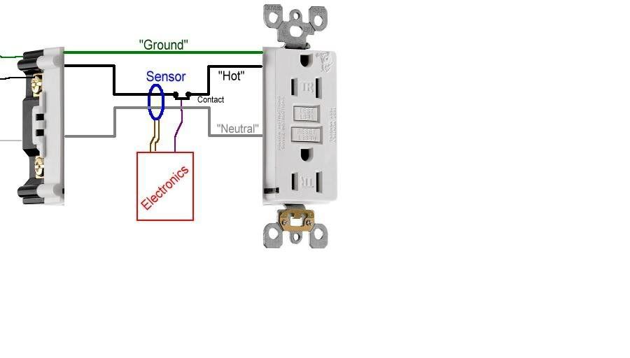
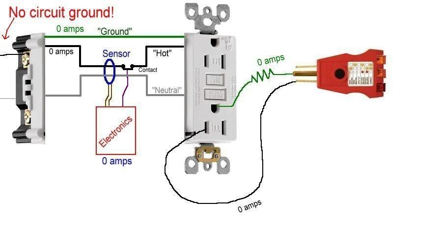
Let's take a standard GFCI receptacle and take it apart. Inside you will find an electronics board (an IC to some of you), a sensor, and a contact. Since the innards of an actual GFCI are quite complicated, I'll use my crude drawing to make things (hopefully) a little more clear.

GFCI1.jpg


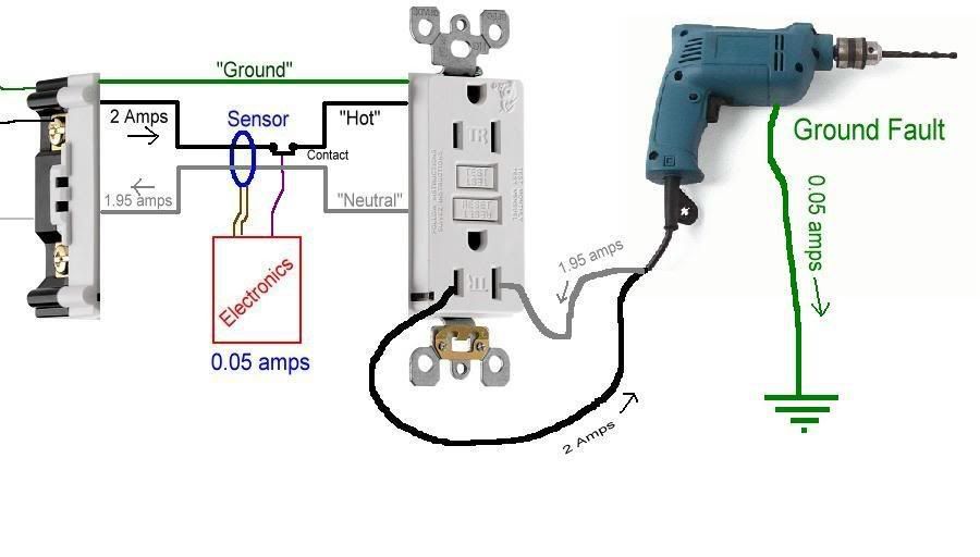
Now, let's plug in a power tool, with the assumption that the tool is safe to use.​


GFCI2.jpg


When you turn the drill on, it draws current through the entire ciruit.... the 'hot' and 'neutral' conductors both have the same amount of current flowing through them, only in opposite directions.​


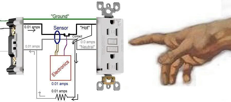
GFCI5.jpg


Since the same amount of current is flowing through both the hot and neutral, they will cancel each other out and the sensor will detect 0.0 amps. If this sensor detects more than 0.005 amps (5mA), then the electronics picks this up and will open the contact, turning power off to the outlet.


So let's do just that. Let's say there's a problem with the cord or the metal case of the drill (yea, I know, the drill looks like it's plastic, but let's pretend it's metal), and a ground fault exists between it and a ground. Now, current will flow through the hot, and to the ground fault. Let's say the fault current is 0.05 amps.​


GFCI6.jpg


The drill will still run properly, but part of the current it consumes does not return through the proper path (the neutral). Instead, it flows through the ground fault.


The sensor will detect an imbalance of 0.05 amps, and the electronics will open the contact and turn of the power.


This is the primary and sole function of GFCI protection. It is assumed a ground fault is going through a human being and turn the power off. Only when the fault is removed will the ability to restore power with the 'Reset' button work. The GFCI does not care whether there actually is a human getting shocked or not. It could be the end of a cord is lying in a puddle of water. It could be a fault the operator of the drill is not a part of. Nonetheless, once more than 0.005 amps flows through a ground fault, the GFCI opens.


Now, in order to test a GFCI receptacle, the manufacturers put in a handy-dandy Test button. What this test button does is create a small current flow (using a resistor to simulate a load with a ground fault) that intentionally bypasses part of the sensor, forcing it to sense that imbalance. If the GFCI sensor, contact, and electronics are functioning properly the power will be shut off.


GFCI7.jpg


Now, up until this point, you will notice the 'Ground' wire has not been mentioned, nor has any current flowed along it. Point is, none needs to. The ground wire is there to open the breaker or fuse if there is a fault within the wiring beyond the receptacle. If the drill was shorted internally, then the ground would carry enough current to cause the breaker or fuse to open and turn off the power. The ground wire is for the operation of the breaker or fuse, NOT the GFCI. If no ground wire existed to feed this receptacle, the GFCI will still function as designed...... sensing imbalances and turning power off in a ground-fault situation.


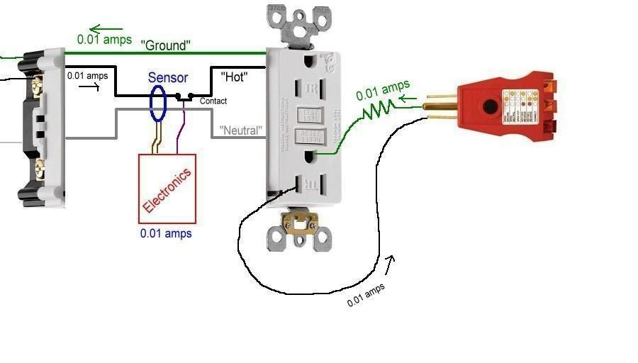
The only function a ground wire has in the operation of a GFCI is when a plug-in tester is used to test a GFCI. One important note here; the industry standard is to use only the built-in Test button to check for proper function. UL does not recognize using plug-in testers as a proper method of testing GFCIs.


GFCI8.jpg


With a properly-wired (3-wire) GFCI receptacle, the only way a plug-in tester can safely simulate an imbalance is to induce it through the ground. It has to, since it cannot bypass the sensor using the neutral. If you placed the resistor between the hot and neutral, the GFCI would only 'see' it as any other load, as the current flow between the hot and neutral would be equal and cancel each other out at the sensor.


With the plug-in tester, the current flows out through the hot, and back through the ground. Since current flow on the ground is not going through the sensor, only the current on the hot is detected. With no opposing return current flow to balance it out, the electronics assume a ground fault and opens the contact... turning power off.


If you only have a 2-wire (ungrounded) circuit, then the plug-in tester cannot create a current flow on the ground as the ground is not there. Since no current can flow in this incomplete circuit, the GFCI will sense 0.0 flow and not open the contact.​


GFCI9.jpg


There are other things today's GFCIs do that are not relevant to the discussion here, but I'll mention them here.


One is Loss of Neutral. The electronics can sense the loss of the circuit's neutral, and will open the contact. The reason being, if there is no neutral, the electronics cannot fuction in order to open the contact in the event of a ground fault. So if the neutral feeding the circuit opens, the GFCI will turn the power off.


Another is a self-test function. If the internal wiring of the GFCI becomes damaged (either physically or, say, a surge due to lighting), the power will shut off as well. Pushing the Reset button will not reset it.... it will stay off and need to be replaced.


Another important function is Line-Load and Hot/Neutral Miswire detection. If the power to the receptacle is mistakenly attached to the Load terminals, or if the hot and neutral are reversed on the Line terminals, the GFCI will detect these installation errors as well and will not turn on until the problem(s) is (are) corrected. This is to ensure the GFCI is wired correctly at initial install to provide proper protection for the life of the unit.


Most GFCI receptacles today are also Tamper-Resistant (notice the TR on the face) to keep foreign objects from being pushed into the slots, and GFCIs are available in Weather-Resistant versions for installation in damp and wet locations.


OK, school is out.
thumbsup.gif

Excellent. Only suggestion I have is to change your drawings to put a contact in the neutral also. I'm 90+% positive all GFCI's open both poles when tripped. Only makes sense to do so - lets say GFCI trips because there is more current on neutral than on hot. That current is coming from outside the supply somewhere and possibly finding a path through the protected load. If the neutral doesn't open when the GFCI trips that outside current will not be interrupted and will continue to flow through the (not so) protected load.
 
post was too long

post was too long

Never had this happen before - my last post wouldn't post because it was too long, The long quote from 480sparky is likely what killed it - but it was very good information here is the rest of what I tried to include in that post:

I have a 2 wire system w/ GFCIs here. How did you trip the receptacle with a wiggy? I could see it being done with a three wire system, but not a 2.
Quite simple test from the hot conductor to anything that is not a path back through the GFCI. Could even be another hot conductor that is 240 volts to the GFCI protected hot or GFCI neutral to any other hot not protected by the GFCI - anything that will create an imbalance of current in the GFCI's current sensor will trip it - read on.


I have a couple ideas of what may be possible in the OP.

First one is not as likely since OP has replied that this is a 1995 home and there is no two wire cabling but still needs consideration just in case something really wierd has happened : bootlegging the EGC for downstream protected outlets would not trip the GFCI when using the test feature on a plug in GFCI tester. It would however result in what may seem like nuisance tripping if you plug in loads that have a three wire cord and enough exposure of grounded surfaces that if they contact other grounded objects enough neutral current will flow outside the desired current path it will trip the GFCI.

Second idea - which if a 1995 home seems really possible is line and load is reversed on the GFCI that is protecting these downstream outlets. (Now it is coming to me that that still may not be possible though but don't give up on this road yet) If the GFCI has one set of hots and one set of loads and they are reversed the GFCI will trip but will not remove power from the receptacle face because it is connected to the load side terminals - if downstream receptacles are improperly connected to the "line" terminals they should still lose power when it trips. Maybe you have multiple cables in the GFCI device box and they are not landed in the right places contributing to the problem. Regardless of whether or not you test the function of the GFCI with the "TEST" button, it must trip if more than 4-6 mA is flowing outside the intended current path, if it doesn't trip something is wrong and it is likely not the GFCI device itself but rather an installation problem.
 
I don't care that the only "approved" test is to use the test button on the device, and what you point out is some of what backs up my reasoning. Some have mentioned low impedance voltage testing devices - they usually draw enough current to be above GFCI tripping levels. I trust them more than the test button - especially on older generation GFCI's. I have some ideas of what may be happening in OP and will get to them shortly.

That makes sense, ignore the correct and calibrated test and go with a wiggy to ground.

Let's not even consider a wiggy draws much more mA than the correct testing level.
 
A wiggy or digital lo-z is fine for getting the lay of the land, but a proper test should be done before declaring a GFCI healthy.

A wiggy works with any path, it doesn't have to be an EGC. Water pipe, dirt, concrete, extension cord plugged into a known good ground. The only catch is that we don't know the resistance of the wiggy, much less the wiggy in series with whatever return path is handy.
 
That makes sense, ignore the correct and calibrated test and go with a wiggy to ground.

Let's not even consider a wiggy draws much more mA than the correct testing level.
You can always press the test button to check it the "correct way" If you go back to the OP the receptacles in question was not known if there was GFCI protection or not. A simple test current that involves current passing outside the normal supply will trip a working GFCI. Since he did find GFCI's in the circuit but they did not trip they are likely miswired since they do work when using the test button (I think that was done) If an intentional fault will not trip the device would you trust the device to protect you when it is necessary for it to do so? It is not the "approved" method of testing but it is still fault current that should operate the device.

A wiggy or digital lo-z is fine for getting the lay of the land, but a proper test should be done before declaring a GFCI healthy.

A wiggy works with any path, it doesn't have to be an EGC. Water pipe, dirt, concrete, extension cord plugged into a known good ground. The only catch is that we don't know the resistance of the wiggy, much less the wiggy in series with whatever return path is handy.

Exactly. The current involved in using the device's test button is likely between the 4-6 mA range so you get the idea it is working at its lowest protection level. Anything higher had better trip it or something is not right.


One is Loss of Neutral. The electronics can sense the loss of the circuit's neutral, and will open the contact. The reason being, if there is no neutral, the electronics cannot fuction in order to open the contact in the event of a ground fault. So if the neutral feeding the circuit opens, the GFCI will turn the power off.​

Are you sure about this? I'll have to review my notes, but I seem to remember that if you open the neutral feeding a GFCI outlet (not a panel breaker GFCI), its own electronics won't be powered up, and thus can't trip its internal breaker with an imbalance.

Or am I missing something important?
 
I did use the trip button and it worked. The one thing I didn't do and should have was pay attention to how the GFI recept was wired. I didn't pay careful attention because the 3-prong tester showed me "correct" for the wiring throughout the circuit. Given the limitations of those testers though, I was working on a dangerous assumption. It won't happen again.

Considering that it could have been a GFI that required more than 4-6 mA to trip, I find it frustrating at times that we really don't have many options for comprehensive GFI testing like the installation testers they use in other countries which give a good indication of how much leakage a GFI/RCD needs before it trips (some use a sweep test, others use timed, preset mA leaks). The only tester I've seen here that does it is the Greenlee 5708I which has 3, 5, 6, 7 and 10 mA test settings, but costs upwards of $300 and doesn't really do anything other than test GFIs.
 
Last edited:
Sounds like the original installer terminated the load conductors on the line screws instead of the load terminals, hence the GFI would trip, but the load would not because it did not pass through the GFI.
 
I did use the trip button and it worked. The one thing I didn't do and should have was pay attention to how the GFI recept was wired. I didn't pay careful attention because the 3-prong tester showed me "correct" for the wiring throughout the circuit. Given the limitations of those testers though, I was working on a dangerous assumption. It won't happen again.

I'm imagining the circuit diagram in my head, but I'm thinking that you can wire a GFCI outlet on a 2-wire circuit with a bootleg ground, and the GFCI will test as having propery polarity and ground using a 3-light tester. I'm pretty sure you can trip it with an external GFCI test button on a "fancy" 3-light tester, and it's own built-in test button will trip properly. I don't think this wiring error will cause a current imbalance and trip the GFCI prematurely, but I'll have to draw this out and trace the circuit before I'm confident enough to postulate a hypothesis and set up a test.

I'm also thinking this GFCI outlet could even be mis-wired with a RPBG condition (Reverse Polarity Bootleg Ground) and it would still test as OK with a 3-light tester as well as the external and internal GFCI test buttons. And there would be no way to check for this "hot ground" condition without an external earth reference (DMM or solenoid tester on a copper pipe or test wire back to the panel bonding point or NCVT such as a VoltAlert). However, the GFCI in the branch circuit should protect consumers from an RPBG chassis shock resulting from a hot ground since that would create an unbalanced load condition and still trip at 5 mA fault current or thereabouts. There may be one mis-wiring condition that would appear to be wired correctly at first glance and check out properly with internal and external testers, but would actually disable the GFCI function. However, I'll have to draw this diagram out completely and set up a test to be sure.

While I've got to believe that no licensed electrician would do a bootleg ground on a GFCI knowingly, there's a real possibility that a DIY homeowner or plant maintenance guy could find what he thinks is a non-grounded outlet that's actually protected by an upstream GFCI receptacle or panel GFCI, and decide he's going to "ground" it with a bootleg jumper.

I'm not bringing this up as an electrician's or inspector's code issue, just as troubleshooting intel since there's a LOT of strange wiring problems in older homes and churches where I've wondered just what were they thinking? With enough knowledge of how forced wiring errors test using your meters, you can get a jump on troubleshooting real world errors. Although, I've got to admit I've seen a lot of wiring errors that I would have a hard time imagining.
As I say in my sound installers classes "You can't make this stuff up"! :slaphead:
 
Status
Not open for further replies.
Top