I don't. It's an irrelevance.Given a VFD and a motor, a motor that powered without VFD exhibits a significant power factor, if that power factor disappears (becomes insignificant) when powered through the VFD, to what do you attribute the PFC?
You are using an out of date browser. It may not display this or other websites correctly.
You should upgrade or use an alternative browser.
You should upgrade or use an alternative browser.
Single Phase current draw for a 3 phase output VFD: technical discussion
- Thread starter Jraef
- Start date
- Status
- Not open for further replies.
For those interested in one advantage of firing angle control of a vsc ref Patel and Holt
they develpoed a method in the early 70's to mitigate harmonics by manipulation of firing angle (among other parameters)
a vsc (or csc) can be used for much more than freq conversion
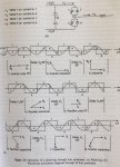
attached is a diagram showing the pf of various converter sections by firing quadrant
as can be seen by the phasors the rectifier can be induct, cap, resist (lag, lead, unity)
they develpoed a method in the early 70's to mitigate harmonics by manipulation of firing angle (among other parameters)
a vsc (or csc) can be used for much more than freq conversion
attached is a diagram showing the pf of various converter sections by firing quadrant
as can be seen by the phasors the rectifier can be induct, cap, resist (lag, lead, unity)
Attachments
Interesting but of what relevance to the thread topic?For those interested in one advantage of firing angle control of a vsc ref Patel and Holt
they develpoed a method in the early 70's to mitigate harmonics by manipulation of firing angle (among other parameters)
a vsc (or csc) can be used for much more than freq conversion
attached is a diagram showing the pf of various converter sections by firing quadrant
as can be seen by the phasors the rectifier can be induct, cap, resist (lag, lead, unity)
Interesting but of what relevance to the thread topic?
firing angle is used with pwm which answers your question, or more precisely your belief firing angle has no relevance to pwm power devices
the diagram show the rectifier is a C load at some points and affects pf
my post is probably more relevant than your critique of mine, the readers will decide
and likely as relevant as many others in this thread
what is your point and why do you care and w i t h made you arbitrator of relevace lol
the premise of the post is rather silly
does a linear relationship exist between i in and i out for a 1 ph in / 3 ph out converter
is power in ~ power out + losses
for avg rms value
and can this be used to size the vfd for 1 to 3 ph application
1.732 is a good base number
considering losses 2 is a good rule of thumb
verify 1 ph line i < vfd i rating
select next std size
previous posts show that is the guidance from mfgs
this horse has been beat to death and resurrected
as I showed in the model both are true
but we knew that
Last edited:
I'm very familiar with firing angle control. It is not relevant to PWM ccontrol.firing angle is used with pwm which answers your question, or more precisely your belief firing angle has no relevance to pwm power devices
the diagram show the rectifier is a C load at some points and affects pf
my post is probably more relevant than your critique of mine, the readers will decide
and likely as relevant as many others in this thread
what is your point and why do you care and w i t h made you arbitrator of relevace lol
the premise of the post is rather silly
does a linear relationship exist between i in and i out for a 1 ph in / 3 ph out converter
is power in ~ power out + losses
for avg rms value
and can this be used to size the vfd for 1 to 3 ph application
1.732 is a good base number
considering losses 2 is a good rule of thumb
verify 1 ph line i < vfd i rating
select next std size
previous posts show that is the guidance from mfgs
this horse has been beat to death and resurrected
as I showed in the model both are true
but we knew that
Can we leave it at that?
I'm very familiar with firing angle control. It is not relevant to PWM ccontrol.
Can we leave it at that?
no, we can't let an incorrect statement stand
firing angle control IS used with pwm, so very relevant
Then I shall let you continue to believe that.no, we can't let an incorrect statement stand
firing angle control IS used with pwm, so very relevant
Then I shall let you continue to believe that.
you are not 'allowing' anyone to believe anything
thought control, lol
silly

- Location
- Placerville, CA, USA
- Occupation
- Retired PV System Designer
As is often the case, I think that you are both right in your own way.I'm very familiar with firing angle control. It is not relevant to PWM ccontrol.
Can we leave it at that?
Firing angle control of the VFD output elements is not particularly relevant since the pulse frequency is so much higher than both the rectifier input frequency and the effective (smoothed) output frequency.
But if the input devices are controlled rather than just passive diodes, then controlling the conduction period of those input elements with respect to the incoming line waveform could easily be used to modify the effective input distortion PF, but probably at the cost of lowering the DC bus voltage for the same AC input.
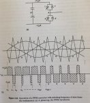
The diagram In gives seems to be showing incidentally that by using snubbing diodes it is possible to get an output current which is greater than the input current, just as is commonly done with a switching power supply.
Other than that, I am inclined to agree with what you thought you were saying.
")
Last edited:
Converter. Not inverter.Firing angle control used on a pwm converter for harmonics mitigation
it is also an inverterConverter. Not inverter.
fiy
the original unedited post said converter
lolFiring angle control used on a pwm converter for harmonics mitigation
Harmonic mitigation is usually on the line side of the converter stage of VFDs these days.it is also an inverter
fiy
the original unedited post said converter
lol
Last edited:
Harmonic mitigation is usually on the line side of the converter stage of VFDs these days.
or by manipulating firing angle (among other parameters)
I guess the discussion is closed.or by manipulating firing angle (among other parameters)
No problem.
If current for active power taken by motor on single phase side is required, the formula used is okay. But if actual current is required on single phase side for harmonics calculation for imposing penalty by POCO, then that formula can not be used.In the interest of fairness, I am opening a new thread here based on side band discussions that I had removed from a previous thread as not being germane to the OP's question, and I have closed that thread because the OP's question was already answered before this tangent ensued.
http://forums.mikeholt.com/showthread.php?t=184058 for reference.
So as a service to valued members who think I am wrong, I am allowing them to show me how that is, because I have been teaching this very issue for 10+ years and if I am indeed wrong, I need to change my thinking.
So here is my stated premise on a subject that is basically unique to phase conversion equipment.
Given: Voltage is equal (230V for argument sake, because that is primarily where this takes place). Motor is 3 phase, lets say the load is 10kW to try to make things easier with nice round numbers. Input to the VFD is 230V single phase, output of the VFD is 230V 3 phase. VFD input power factor is .95
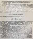
My premise: Input current TO THE VFD is equal to the Output current to the motor x 1.732, because of the following well established and published formulae:
Three phase; I = W/V x PF x 1.732 ergo I = 10,000/230 x .95 x 1.732 = 26.42A
Single phase; I = W/V x PF ergo I = 10,000/230 x .95 = 45.76A
45.76/26.42 = 1.732
So tell me where and why this does not apply.
Hmm. The displacement power factors PF in the three phase side and single phase side as used in the formula may not be same in reality!If current for active power taken by motor on single phase side is required, the formula used is okay.
jpeer
Member
- Location
- Cape Coral, Fl
How to calculate three phase to single phase power
How to calculate three phase to single phase power
It’s relatively simple to make 3 phase power calculations.
In operation, two single phase lines of current are distributed among three output lines of power from the phase converter. To calculate what input power is needed, the square root of three (1.732) is used as a multiplier of the three phase current value found on the motor data plate. The resulting value is the amount of power, expressed in amps, required at the input side of phase converter.
Here’s a simple example of the equation:
You’re preparing to drive a three phase low-horsepower motor rated at 10 amps.
Single phase to 3 phase power calculation input requirement = The square root of 3 (1.732) x 10 amps
= 1.732 x 10 amps
= 17.32 Amps
Single phase power input in this instance is 17.32 Amps
This has been taken directly from: North America Phase Converters web page.
Jraef is right.
You have ignored power factor.
It can be quite different between input to a rectifier bridge and output to a motor.
gar
Senior Member
- Location
- Ann Arbor, Michigan
- Occupation
- EE
170609-2434 EDT
jpeer:
If I have a black box device that is 100 % efficient (meaning no power loss in the black box), it produces 3 phase power to an unbalanced load, even asume the load is resistive, then what is the load current I use for you to apply the 1.732 factor to? And further does this even imply that the input current to the black box is sinusoidal?
You just can not arbitrarily apply equations and constants to a circuit without knowing details of the circuit.
.
- Status
- Not open for further replies.