Single Phase Dual Secondaries in Parallel - Generator

Merry Christmas
Status
Not open for further replies.

JPinVA

Senior Member
Location
Virginia
I'm looking for thoughts and any operational feedback anyone may have on the following conundrum of mine.

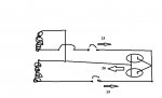
I have a generator that uses dual secondaries and a switch that allows the user to switch from 120/240 to 120 only. In the latter, the coils are connected in parallel, which removes the 240 phase to phase and replaces it with a single 120. This switch effectively puts the OCPDs (one in each leg) in parallel as well. These feed a 20A dual receptacle.

Each OCPD is 13.5A. When the coils are in series (i.e., 240 line to line with a center neutral), any current over 13.5 (on either leg) will trip the OCPD.

When the coils are in parallel, a current load as high as 27A (13.5 + 13.5) is the trip threshold. For the sake of argument, let's assume the designer/builder of the generator has properly sized everything internally to handle 27A. So we're not talking about frying the generator.

Now the conundrum: What protects a user from plugging a 20A cord (or, ahem...a 15A cord) into the receptacle, and subsequently overloading that cord to the tune of 26A? Even a somewhat savy consumer, looking at the wiring diagram showing the 13.5A breakers, might be misled.
 
I think the problem is that your understanding of current flow from that generator is flawed. You have EITHER, two separate 120V circuits each capable of 13.5A, or one 240V circuit, capable of 13.5A. you would not refer to the 240V circuit as "13.5 + 13.5 = 27A", it is just 13.5A @ 240V. The only difference in the OCPDs would be that for the 240V, the poles would have a "common trip", but for the 2 x 120V circuits, each would be separate. If you have 13.5A OCPDs and someone tries to hook up a load that draws more than 13.5A (nominal), one or both OCPDs will trip.
 
Ok. Before we go further, I'm going to re-look at that wiring diagram and run a test. Might be this weekend before I get to it. I'll be back.
 
I think the problem is that your understanding of current flow from that generator is flawed. You have EITHER, two separate 120V circuits each capable of 13.5A, or one 240V circuit, capable of 13.5A. you would not refer to the 240V circuit as "13.5 + 13.5 = 27A", it is just 13.5A @ 240V. The only difference in the OCPDs would be that for the 240V, the poles would have a "common trip", but for the 2 x 120V circuits, each would be separate. If you have 13.5A OCPDs and someone tries to hook up a load that draws more than 13.5A (nominal), one or both OCPDs will trip.

I was trying to say that, but failed.:slaphead:
 
Ok, here's a diagram. Discuss. Well, discuss the technical merit, not my artistic merit. The OCPDs are each 13.5, which will allow 13 on each leg that can deliver 26 across the load. I confirmed the 120 switch connects the hots (via continuity check) at the same time it parallel's the coils.
 

Attachments

  • circuit.jpg
    circuit.jpg
    27.9 KB · Views: 3
Here is a good link that explains series and parallel secondaries. It is for transformers. but principals are the same..

https://www.electronics-tutorials.ws/transformer/multiple-winding-transformers.html

Series

trans61.gif


Parallel

trans62.gif
 
I'm not understanding the reason for the switch which is I think what is confusing. Paralleling the windings will double the output current but for what reason? Separate or parallel the available current is the same, limited by the breakers on either receptacle. It's essentially two breakers in parallel. If the weaker one trips the other will follow.


-Hal
 
Last edited:
I'm not understanding the reason for the switch which is I think what is confusing. Paralleling the windings will double the output current but for what reason? Separate or parallel the available current is the same, limited by the breakers on either receptacle. It's essentially two breakers in parallel. If the weaker one trips the other will follow.


-Hal
If the two secondaries are not wired with a common point to serve as a center tap, there will be no 240V supply available. No problem there.

Since NEMA receptacles are voltage specific, I do not see a situation where a single receptacle could be used to provide either 120 or 240, except where a four pole (120/240 with neutral and EGC) receptacle is used to plug in both 120V and 240V loads.
I see the OP's concern if indeed there is one hard wired OCPD for each winding and there is a switch that allows the two windings to be put in parallel to feed a single 120V load.
To make the configuration work and be code compliant, there would have to be a separate 27A (i.e 30A) 120V-onlyreceptacle which is only energized when the windings are in parallel. Trying to feed the parallel winding configuration either to a 120V 20A receptacle or to one side only of a 120/240V 20A receptacle would create the possibility of overloading the receptacle, while not overloading the generator.
 
From Honda:

Voltage Selector Switch

The voltage selector switch gives you more usable power from the 120V outlets and added flexibility. It allows you to choose between using both 120 and 240 Volts, or 120 Volts only.

Selecting 120V only allows for the total generator output to be available through any of the 120 volt outlets. This enables you to power units with larger wattage requirements.

What’s the difference between 120V/240V and 120V only?

On a typical 120V / 240V generator, each of the 120V outlets gets only half of the generator’s capacity. For a 5000W generator, that would be only 2500W at any given 120V outlet. The full 5000W is only available at the 240V outlet. This limits the amount of 120V power you can use.

But with a Honda voltage selector switch, you can essentially turn off the 240V outlet. This means the full 5000 watts are available from the 120 V outlets, limited only by the capacity of the individual outlet.

Bottom line

The voltage selector switch gives you more power from the 120V outlets. And because most appliances are 120V, it means your Honda generator can power more.

https://powerequipment.honda.com/generators/120-240-selector
 

Thank you..and Honda. They did a good write up there. And they sustain my original conundrum. The current AVAILABLE to the receptacle EXCEEDS the receptacle's spec. The Honda instructions state it is the user's responsibility to ensure the receptacle is not overloaded. OCPD does NOT provide overload protection for current that exceeds the spec (exceeds 20A on the Honda generator) and is below the the combined OCPD (25A).

I suspect (or I would hope) the Honda receptacle (while spec'd for 20A) is actually designed to handle 25A. Which leads us back to my original conundrum...the rating of the power cord running the load. This is even more of a concern considering we're talking portable generators, where use during a power outage might be more inclined to task it with high loads.
 
I borrowed Honda's way of displaying the configuration, and incorporated the numbers from my generator, along with the location of the OCPDs. This figure is electrically the same as my previous figure, but arranged in a manner that makes the flow more clear.

Each OCPD triggers at 13.5A. As you can see, 13A can flow from each coil, delivering 26A to the duplex outlet, with the hots connected. The full 26A can be delivered in any combination to the loads served by the connected cords, including the full 26A on one cord, and zero on the other.

circuit 2.jpg
 
I borrowed Honda's way of displaying the configuration, and incorporated the numbers from my generator, along with the location of the OCPDs. This figure is electrically the same as my previous figure, but arranged in a manner that makes the flow more clear.

Each OCPD triggers at 13.5A. As you can see, 13A can flow from each coil, delivering 26A to the duplex outlet, with the hots connected. The full 26A can be delivered in any combination to the loads served by the connected cords, including the full 26A on one cord, and zero on the other.

View attachment 21322

Looks that way. If a listed genny, then not much you can do I suppose. IDK.
 
Actually, your outlets are usually specced to handle more than thirty amps of current if needed... which is why you often see thirty amp circuits feeding fifteen and twenty amp outlets in factories... because the sharing of the circuit by several devices at one Time brings the actual amps per outlet down... think New York used to do this all the time. I remember my uncles home in the Bronx had no fifteen or twenty amp fuses in it. In UK you use a 30 or 32 amp breaker on two of the outlet circuits, the ring and the one radial, and that is with thirteen amp outlets..no twenty amp outlets here.
 
Actually, your outlets are usually specced to handle more than thirty amps of current if needed... which is why you often see thirty amp circuits feeding fifteen and twenty amp outlets in factories... because the sharing of the circuit by several devices at one Time brings the actual amps per outlet down... think New York used to do this all the time. I remember my uncles home in the Bronx had no fifteen or twenty amp fuses in it. In UK you use a 30 or 32 amp breaker on two of the outlet circuits, the ring and the one radial, and that is with thirteen amp outlets..no twenty amp outlets here.

I disagree. I know of no section in the NEC that allows 15A or 20A recs on a 30A breaker and I do not believe those recs are listed or speced for 30A.
 
Good discussion. I'll throw out some recommendations and comments.

If anyone here interfaces in some way with a customer who uses a portable generator, and you note that it has one of these switches, you might want to note the need to not overload the outlet, and to use a 10 Gauge extension cord.

I guess if this was a major problem, we would see a bunch of reports on fried extension cords and fires.

It does seem a bit risky from a liability standpoint, but I get the feeling many of these gen manufactures already operate "on the edge" as it is. Delivering six amps over rating sounds like one of those trade-offs between feature/function and safety.

As for listing, it has CE stamp, but that isn't recognized by NEC. Mine has a floating neutral (because I don't switch neutrals in my TS), and UL does not list any gens under 15KW that float the neutral. Ostensibly, this is because they see portable generators as job site power, or cord-connected backup, supplies where the generator neutral/ground bond is needed for ground fault protection. It's also why a float isn't OSHA compliant. But I digress.

[Side note: The fact the generator floats the neutral AND has the power switch raises the issue of the danger of the melting extension cord. A short to the EGC will energize the chassis and might not trip the breaker!!!]

I run my power split phase via a 10 Gauge L/R14-30. Split phase, my max amps are 13.5. If I go 120 (and lose one leg), I can get as much as 26A on the other leg, but my 10 Gauge is good. That said, at that point, voltage drop becomes a concern. All said, I try to run it half load anyway.

Back on topic....I pretty much know what I'm doing. But I have a good chunk of experience and understanding. Allowing Joe Blow user the ability to overload an extension cord to the point of melting the insulation...well...I don't know. As I said, we don't see an epidemic out there. So maybe Murphy just hasn't come calling yet.

Just a note. If you come across one of these, do a courtesy look at the cord being used by the customer, and make an appropriate safety suggestion/recommendation. If the generator is floating, and they don't intend on hooking up via a TS that completes the bond, then you might also recommend bounding the neutral.
 
I did some additional testing. Results and comments FYI below:


I'll refer to the two power terminals on the 14-30 as the X terminal (XT) and Y terminal (YT). As for the duplex outlet, I'll refer to the top receptacle hot as D1 and the bottom receptacle hot as D2.


Continuity testing. Generator off. When in 120/240 mode, D1 has continuity with XT and D2 has continuity with YT. When in 120 mode, D1 and D2 both have continuity with XT and each other. YT has no continuity with any node.


Voltage tests. Generator on. The observed voltages are complementary to the continuity tests made above.


120/240 Mode
XT to YT: 240
XT to D1: 0
XT to D2: 240
YT to D1: 240
YT to D2: 0
D1 to D2: 240
XT to N: 120
YT to N: 120
D1 to N: 120
D2 to N: 120


120 Mode
XT to YT: 0
XT to D1: 0
XT to D2: 0
YT to D1: 0
YT to D2: 0
D1 to D2: 0
XT to N: 120
YT to N: 0
D1 to N: 120
D2 to N: 120


Comments:


The two zero measurements in 120/240 are because the two nodes are same voltage and same phase. All zero measurements involving YT in 120 mode are due to YT being a stub. All other zero measurements are because the two nodes are same voltage and same phase.


In 120/240 mode, XT and YT form the 240 split phase, with 120 to neutral for each terminal. D1 and D2 are basically analogous to a multi-wire configuration with D1 running off the same tap as XT and D2 running off the same tap as YT. Hence, D1 to D2 is 240.


In 120 mode, the Y tap is connected to neutral (i.e., the X coil tap that is neutral in 120/240 mode) at the same time the neutral tap on the Y coil is connected to the X tap. This is the essence of the parallel connection described in previous posts. From a design standpoint, there are three ways to handle YT. Leave it connected to the Y tap (now neutral), switch it to the X tap(providing 120V to neutral at the YT connection), or disconnect it altogether. In the generator under test, it is the latter case. YTis disconnected altogether and exists as an unterminated stub. D1 and D2 are connected together like a standard duplex fed by one common 120 hot. In this case, the same tap as the one connected to XT.


If my 14-30 is attached to my house,and the gen is in 120 mode, then the 120 circuits on the X side will have 120 available from the conductor connected to XT. The Y side conductor will have zero potential as YT is open. There is no 240 so those won't work at all. If I have any X side devices that pop the 13.5 breaker in 120/240 mode, then I have the option of switching to 120 mode to run the X-side devices, at the expense of dropping everything on the Y-side, as well as losing all 240 circuits.


Note that in 120 mode, the neutral current is additive. It carries the full combined current off of both coils...up to 27 amps. The X conductor on the 14-30 carries the same as the neutral. As the 14-30 is rated at least 30A(as used),the 27 amps on the X phase and the neutral should not be an issue.


The 120 switch is advertised as "Power Boost Technology, which gives the user the ability to double the power in the generator". This is a somewhat tricky statement,and hinges on the use of the phrase "in the generator"versus "of the generator". The power "of the generator" isn't doubled. The 240 X 13.5 (the 120/240 mode limit) is the same power as 120 X 27 (the 120 mode limit). The power available to two legs in 120/240, is all applied to one leg in 120 mode. So, I guess the equipment manufacture could say the power doubling occurs "in the generator" at one leg, while the other leg is zeroed.


I examined the generator wire diagram,and all connections are consistent with the observations above.


In the grand scheme, it's actually a pretty nice feature....PROVIDED...the user uses an extension cord that can handle the 120 mode current which could be as high as 27A before an OCPD trips.
 
Status
Not open for further replies.
Top