SceneryDriver
Senior Member
- Location
- NJ
- Occupation
- Electrical and Automation Designer
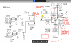
Solar array with 31.25A design current and 35A fuses in fused disconnect (PoCo requirement to see "open blades") currently connected as a line-side tap to a clapped-out 150A service.
Proposed replacement:
200A meter/main with 200A main breaker and (8) breaker spaces and feedthrough lugs.
(2) 125A breakers feed: main panel in house, and critical loads panel (eventually to be generator backed). Single pole breakers to feed panel service receptacles and basement lights (to have power and light if work on any panels is necessary). 200A panel in garage is fed via the feedthrough lugs to accommodate multiple EV chargers in the future.
Solar is backfed through a 40A breaker installed at the opposite end of the bus from the main breaker in the meter/main. My interpretation is that this would meet the 120% rule. Is that correct even when using the feedthrough lugs? The bus stops at the lugs, yes?
Thoughts?
SceneryDriver
")