Solar Inverter tie to house system - 120% Rule help

huronengr

Member
Location
13760
Occupation
Energy Engineer
I have a lot of experience in the industrial industry and not so much in the residential industry. Looking at solar for my house, and the company I'm dealing with seems to be going through a lot of steps that I'm not sure about. I thought it would be as easy as installing a new 240/60A breaker in my panel (SquareD, Homeline, 225A bus, with 200A main breaker).

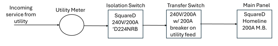
The company is telling me that due to my transfer switch, that they want to tie-in with splicing bugs on the line side of the 240V/200A main disconnect of the house. I'm not a fan of these, would much rather buy additional lug kit from SquareD (but they are not allowed/permitted on the line side of the disconnect). I proposed having the company tie in to the load side of the disconnect but they claimed it would violate the 120% rule and needed to be on the line side.
 
If you have a generator and your PV system does not have batteries, then you must connect the PV on the line side of the transfer switch. It isn't a 120% rule issue, it's because if the PV system and generator are both connected to your panel at the same time, the PV system could backfeed the generator, which would probably damage the generator.
 
... would much rather buy additional lug kit from SquareD (but they are not allowed/permitted on the line side of the disconnect). ...
Second part of that sounds wrong. SquareD equipment that has provisions for those additional lug kits is perfectly code compliant and a good way to tie in. That said, I'm a bit unclear on what equipment you have where.
 
If you have a generator and your PV system does not have batteries, then you must connect the PV on the line side of the transfer switch. It isn't a 120% rule issue, it's because if the PV system and generator are both connected to your panel at the same time, the PV system could backfeed the generator, which would probably damage the generator.
Thanks for the feedback, but the 240/200A isolation switch is in between the meter and the utility feed to the transfer switch so this all takes places on the line side of the transfer switch. Question I have is on the line side of that isolation switch (right after the meter) or the load side of that switch (prior to the transfer switch).
 
Second part of that sounds wrong. SquareD equipment that has provisions for those additional lug kits is perfectly code compliant and a good way to tie in. That said, I'm a bit unclear on what equipment you have where.
When I talked to the SquareD Tech online they said that I can install the AL20DTF lugs on the load side of the disconnect, not the line side. Personally I would rather use the lugs on the line side, and then bring 3/0 wires to the solar disconnect load side but I"m stuck with what SquareD said.
 
Second part of that sounds wrong. SquareD equipment that has provisions for those additional lug kits is perfectly code compliant and a good way to tie in. That said, I'm a bit unclear on what equipment you have where.
I believe if you look up 'SquareD AL20DTF' if mentions that load side only.
 
Thanks for the feedback, but the 240/200A isolation switch is in between the meter and the utility feed to the transfer switch so this all takes places on the line side of the transfer switch. Question I have is on the line side of that isolation switch (right after the meter) or the load side of that switch (prior to the transfer switch).
I guess I am confused. It seems to me that you are saying that the "isolation switch" (do you mean the service disconnect?) is on the line side of the utility meter. If that is the case I don't think you can connect to it at all.
 
OP, you are leaving out a lot of information people need to know to help you.
  • Is the "isolation switch" the service disconnect or a cold meter isolation switch?
  • Is there an existing whole house back up generator?
  • Is the transfer switch also the service disconnect?
  • Is there another disconnect other than the transfer switch or isolation switch that is the service disconnect and if so, where is it located in the system?
This. It would help if you (the OP) used the correct term for what you are calling the "isolation switch". Using the correct terms is key to effective communication. Also, if you could furnish a correctly notated drawing of the system it would help us to help you.
 
Sorry for the lack of clarify and appreciate the feedback. Diagram below (hopefully). I was always told to call the switch an 'isolation' switch because it isolates the utility from the transfer switch. Simple drawing from power point, hopefully illustrates what I'm working with:

1750268145241.png
 

Attachments

  • 1750263032401.png
    1750263032401.png
    23.7 KB · Views: 2
If it were my own home what I would do is get a double lug kit for the load side of the utility meter, most meter manufacturers offer them, if I could not find one I'd install a one that had them. A class 320 meter as it has them by default.
Then I'd add a 2nd 60A or 100A disconnect call it service disconnect #2 and the 'isolation switch' is labeled service disconnect #1 .
The service disconnects would be grouped in one location, and perhaps the GES would need to be updated if there is a water pipe.
I'd let the solar guys take it from there.
 
Sorry for the lack of clarify and appreciate the feedback. Diagram below (hopefully). I was always told to call the switch an 'isolation' switch because it isolates the utility from the transfer switch. Simple drawing from power point, hopefully illustrates what I'm working with:

View attachment 2578246
I agree with placing the solar tie-in prior to the transfer switch. I would like to use the lug kit mentioned above, but on the load side of the isolation switch disconnect (not the line side).
 
If it were my own home what I would do is get a double lug kit for the load side of the utility meter, most meter manufacturers offer them, if I could not find one I'd install a one that had them. A class 320 meter as it has them by default.
Then I'd add a 2nd 60A or 100A disconnect call it service disconnect #2 and the 'isolation switch' is labeled service disconnect #1 .
The service disconnects would be grouped in one location, and perhaps the GES would need to be updated if there is a water pipe.
I'd let the solar guys take it from there.
That's exactly what I want to do. Solar Vendor engineer is telling me it has to be on the line side of the existing isolation switch. SquareD is telling me they don't make lugs for the line side, only the load side.
 
I agree with placing the solar tie-in prior to the transfer switch. I would like to use the lug kit mentioned above, but on the load side of the isolation switch disconnect (not the line side).
In this case you would be making a feeder tap connection per 705.12(A) and the 125% rule does not apply. What is your maximum inverter current?
 
As I see it the 'isolation switch' is your service disconnecting means. Adding lugs on the load side of it can work, although there are some additional rules to follow. For example you'd need to protect the existing feeder downstream, which might require a 200A breaker in the ATS, if there isn't one there already.

The solar could be done as a tap to a fused disconnect. The 120% rule does not apply to the Square D disconnect because it is not a panelboard.

Basically you could connect on either the line or load side of the Square D disconnect, but the exact rules are different.
 
As I see it the 'isolation switch' is your service disconnecting means. Adding lugs on the load side of it can work, although there are some additional rules to follow. For example you'd need to protect the existing feeder downstream, which might require a 200A breaker in the ATS, if there isn't one there already
His drawing shows a 200A breaker on the line side of the ATS.
 
The isolation switch (service disconnect?) ahead of the ATS with 200A utility breaker makes this super easy. I would definitely recommend interconnecting via a feeder tap in either the ATS or the 200A switch, whichever is closer to the inverter, and I would use Burndy Cleartaps to splice into the feeder, and run the tap conductors through a fused disconnect and then to the inverter. We typically use the BIBD-350-2 taps, which are large enough to pass the insulated conductor straight through it without cutting it. Just strip a little insulation off the conductor, slide the tap connector in place, sinch it down, and use the 2nd port to connect your tap conductors. The tap rules get ammended by 705.12, but that will only come into play if the PV system is small. I don't like the insulation piercing connectors and don't use them, but I know they are installed frequently and usually don't cause problems. This type of interconnection will allow you to installed up to 160A of continuous PV inverter current.
 
In this case you would be making a feeder tap connection per 705.12(A) and the 125% rule does not apply. What is your maximum inverter current?
The inverter is 15 kW but I don't have a cut sheet yet. Simple math tells me around 62.5A.
 
The inverter is 15 kW but I don't have a cut sheet yet. Simple math tells me around 62.5A.
If that is anywhere close to accurate you won't have a problem as long as the ATS has an OCPD on the line side.
 
Top