Some basics of VFD install

Status
Not open for further replies.

Electromatic

Senior Member
Location
Virginia
Occupation
Master Electrician
Hello, all. I've worked around VFDs on several occasions and have read much about them but haven't really done installations. I have a customer that wants them on several pump motors. The existing arrangement is a MCC in the room then non-fused disconnects a few feet from the motors then, of course, the motors. The basic plan was simply to come out of the disconnect to the VFD then from the VFD to the motor.

My first question is, should I bypass the MCC controls once the drive is installed? I'll have to take another look, but I don't think there is any inter-connectivity or PLC type operation involved in the MCC.

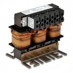
Secondly, I just found out that they want to install line reactors as pictured. Where/how do I mount these? They won't fit in the disconnects. Can I mount them in the MCC? A separate enclosure near the drive? If a separate enclosure, would it need to be vented?

We're not doing any of the drive control wiring or programming. I thought it would be a pretty straightforward moving-around of some line-voltage connections, but now I'm not so sure. It will be good experience with drives, though.

Thanks as always for any help!
 

Attachments

  • l_lr4015 (1).jpg
    l_lr4015 (1).jpg
    31.1 KB · Views: 1
Our usual arrangement was to have all the VSD components in their own enclosure. That included disconnect, usually a door interlocked fuse switch, drive module, line reactors if required, output contactor, control transformer, control relays, terminals, any transducers required, in fact everything the system needed.
 
Our usual arrangement was to have all the VSD components in their own enclosure. That included disconnect, usually a door interlocked fuse switch, drive module, line reactors if required, output contactor, control transformer, control relays, terminals, any transducers required, in fact everything the system needed.
Same here, we get the complete system from an integrator and wire power in and power out.
Allen Bradley can package a drive for you, but our integrator gets a discount from AB and we find it easier to go with them.
If you have room in the MCC, get a new backpanel all wired and ready to go.
The VFD is a motor controller, it will have OL protection, so you won't need any of that.
Some VFDs have a remote monitoring panel that goes in the front of a panel. Our last project the controls and reactor were in an enclosure that sat below the VFD.
 
Look at drive manual

Look at drive manual

Look at the drive manual first before anything is done. I installed a 30 hp drive that wanted a power contactor first as an E-Stop/power contactor, some new drives use safety circuits instead. If you don't know how, don't spec the drive for them there is a lot involved not just " we want a drive here"
 
Look at the drive manual first before anything is done. I installed a 30 hp drive that wanted a power contactor first as an E-Stop/power contactor, some new drives use safety circuits instead. If you don't know how, don't spec the drive for them there is a lot involved not just " we want a drive here"

there is rarely a good reason to put a power contactor on the line side of a VFD. Most VFDs are used in applications like fans or pumps where such an arrangement serves no purpose other than to destroy the VFD.

depending on size you can get a VFD that goes in a std mcc bucket, or have a box made up as another poster suggested.

usually when we make them up the reactors are part of the assembly along with whatever else needs to be there of OCPD etc. if it is ethernet, consider having a door mounted port so you don't have to open the vfd enclosure to configure the vfd via software.
What he said. Don't leave a contactor in the MCC bucket if you can avoid it, and the breaker in an MCC starter is usually an MCP, so it can't be used to feed the VFD, you will have to change it out with a Thermal-Mag breaker.

If it were me, I'd plan on swapping out the breaker in the MCC bucket, removing the starter, then that gives you room for the line reactor. So you would come out of the breaker, into the reactor, out of the reactor into the VFD, out of the VFD into the disconnect, then to the motor. You ALSO should put an aux. contact in the disconnect switch, then wire it back to a "disable" input on the VFD (most have one now) so that if someone opens that disconnect while it is running the motor, the aux contact turns off the VFD output before the contacts open. Otherwise it's another way to damage the VFD.
 
How are these VFD‘s handling power-grid interruptions if they smoke every time they lose power?
 
Same here, we get the complete system from an integrator and wire power in and power out.
Allen Bradley can package a drive for you, but our integrator gets a discount from AB and we find it easier to go with them.
Yes, we were the system integrator designing and rating everything to meet the project requirements as detailed RFQ. Installation and cabling too when requested.
 
How are these VFD‘s handling power-grid interruptions if they smoke every time they lose power?
:thumbsup:

When it comes to E-stop, interrupting the input power to the drive maybe is effective for mechanical reasons as the driven motor will stop fairly quickly. Probably not a great idea to use this as a regular control method though. Even on machinery where regular opening of access doors would operate a safety relay - you wouldn't necessarily want to cut input power to drives with this feature.

Control interlock on the output side of drive if you would put a disconnect in the output is probably more necessary for ensuring you don't close the switch on an active output then it is a problem for opening an active output.
 
How are these VFD‘s handling power-grid interruptions if they smoke every time they lose power?
When a VFD is initialized, the DC bus capacitors must charge up and since they do so almost instantly, the charging current is pulled in at the rate of the available fault current at the drive terminals. This can be so high that it would damage the diode bridge and the caps themselves. So VFDs (and all things with DC bus caps for that matter) must have what's called a "pre-charge" circuit that limits this charging current. In many VFDs, the pre-charge circuit is a current limiting resistor in series with the caps, but to prevent that resistor from causing a permanent voltage drop, it is bypassed after about 1 second with a relay contact. Those resistors do get stressed, even if only slightly, every time the VFD is powered up. As a gross general rule, they are designed for at least 1000 operations, so a grid interruption or opening a contactor once in a while for emergencies is no big deal. But if a drive is de-energized and energized every day, that's less than 3 years before that resistor burns out, even less if that contactor opens every time you turn off a machine.
 
Thanks, everyone, for the input so far; these forums are great!

The customer has already purchased the drives (Durapulse GS3 from automationdirect) and intended to have them mounted in the open near the motors. For the line reactors, it looks like I'll try to put them in the MCC buckets if they will fit and if not, get a separate enclosure for them to put near the drives. Is heat an issue in either location? I can see having an overall enclosure if there were multiple drive accessories, but I don't know if cost and space make sense here.

At the MCC, I'll definitely take the 'starter' portion of the wiring out then see if there are MCPs or breakers.

Contactors are an option for these drives, not a requirement.

My understanding is that I should put the existing disconnect on the line side of the VFD. If I were to put it on the load side, I would need an aux/"disable" contact back to the drive.

Thanks again.
 
When a VFD is initialized, the DC bus capacitors must charge up and since they do so almost instantly, the charging current is pulled in at the rate of the available fault current at the drive terminals. This can be so high that it would damage the diode bridge and the caps themselves. So VFDs (and all things with DC bus caps for that matter) must have what's called a "pre-charge" circuit that limits this charging current. In many VFDs, the pre-charge circuit is a current limiting resistor in series with the caps, but to prevent that resistor from causing a permanent voltage drop, it is bypassed after about 1 second with a relay contact. Those resistors do get stressed, even if only slightly, every time the VFD is powered up. As a gross general rule, they are designed for at least 1000 operations, so a grid interruption or opening a contactor once in a while for emergencies is no big deal. But if a drive is de-energized and energized every day, that's less than 3 years before that resistor burns out, even less if that contactor opens every time you turn off a machine.

What he said :)

But more importantly, it serves no real purpose most of the time. It just adds cost.

If you insist on adding a contactor it should be on the load side and interlocked with the drive enable.

But I go back to why? It serves no good purpose most of the time. It is not a safety issue like some people think. Most of these drives are used on applications like fans where the motion won't stop by interrupting power anyway. It is actually safer to let the drive bring the fan to a stop since it will stop faster than just spinning down. Same thing with a spindle unless you put mechanical brakes on it.
 
For the line reactors, it looks like I'll try to put them in the MCC buckets if they will fit and if not, get a separate enclosure for them to put near the drives. Is heat an issue in either location? I can see having an overall enclosure if there were multiple drive accessories, but I don't know if cost and space make sense here.

I am curious why they bought line reactors in the first place. they are not often actually needed.

At the MCC, I'll definitely take the 'starter' portion of the wiring out then see if there are MCPs or breakers.

If it is an older MCC it may well have TM breakers. Or you may have to replace an MCP with a TM breaker.

Contactors are an option for these drives, not a requirement.

Then leave them out unless your risk assessment demands them.

My understanding is that I should put the existing disconnect on the line side of the VFD. If I were to put it on the load side, I would need an aux/"disable" contact back to the drive.

Yes. There is no reason you cannot use the CB in the MCC as the disconnecting means. It is simpler that way unless you want something closer to the motor.

Thanks again.
Good luck.
 
WIt is actually safer to let the drive bring the fan to a stop since it will stop faster than just spinning down. Same thing with a spindle unless you put mechanical brakes on it.
To get a significant difference in decel time you would need dynamic or regenerative braking.
 
Yes. But you won't get either if you power off the drive.
True but not generally an issue for small/medium sized pumps or compressors. For larger VSDs on pumps, fans, and compressors, we usually used our ISK drives which has regen capability. Even in applications where it is not required.
 
True but not generally an issue for small/medium sized pumps or compressors. For larger VSDs on pumps, fans, and compressors, we usually used our ISK drives which has regen capability. Even in applications where it is not required.

we rarely use regen drives here since they are almost double the cost.
 
we rarely use regen drives here since they are almost double the cost.
Yes, again true. And most applications don't really require it anyway. We manufactured some systems that absolutely did though.
The high speed machine tool drives for example. From 10,000 rpm to zero within half a second on a 56 kW.............
 
You ALSO should put an aux. contact in the disconnect switch said:
That's true as far as what I have been taught. But we do have a bunch of small conveyor drives 1-2hp and the operators routinely
kill the disconnects to turn off a section of conveyor. Mostly out of laziness. None of these drives have had any problems. I am assuming
that maybe the aux contact on small drives isn't actually an issue.
I don't think opening the output circuit of the drive is as much of a problem as closing the switch when drive output is active. So aux contact to drive enable is more critical for not letting drive start unless the switch is closed.

Even with aux contact set to open slightly before the main contacts on the disconnect, if you have drive programmed to decelerate the load to a stop/near stop you are going to interrput output current while decelerating anyway.
 
Status
Not open for further replies.
Top