So I am trying to understand the different terminology for all the bonding jumpers. I understand SBJ is where you bond your secondary neutral to ground. I understand that your main bonding jumper is just connecting egc. I understand egc is just metal parts connected together. Gec is your grounding electrode conductors. I’m getting hung up on SSBJ.
I understand what the 2023 NEC definition says
“ a conductor installed on the supply side of a service with an service equipment enclosure, or for a separately derived system that ensures the required electrical conductivity between metal parts required to be electrically connected. “
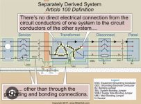
But in the diagram it’s on what I would have thought was not the supply side. Is it the supply side of the secondary because it’s a seperately derived system? Thank you in advance.
I understand what the 2023 NEC definition says
“ a conductor installed on the supply side of a service with an service equipment enclosure, or for a separately derived system that ensures the required electrical conductivity between metal parts required to be electrically connected. “
But in the diagram it’s on what I would have thought was not the supply side. Is it the supply side of the secondary because it’s a seperately derived system? Thank you in advance.