- Location
- New Jersey
- Occupation
- Journeyman Electrician (retired)
If the yellow line is the current flow then yes but it may only be for an instant. The OCPD on the secondary should open.Would current flow like I showed on my edit to this diagram.
If the yellow line is the current flow then yes but it may only be for an instant. The OCPD on the secondary should open.Would current flow like I showed on my edit to this diagram.
The quote you were responding to was predicated on "a bond in more than one location". That means a bond in the secondary system in more than one location, not the fact that you have both an MBJ (for the primary system) and a SBJ (for the secondary system). The diagram has only one bond on the secondary system.Would current flow like I showed on my edit to this diagram. I drew a ground fault at the panel. I assume not but is that what you’re saying kwired? I would’ve thought it would go to XO.
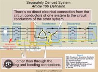
To illustrate the parallel paths, the purple path below is the intended path for ground fault current at the panel on the right, and the orange loop is an alternate segment that is parallel with the SBJ, and so would carry a little current.However, that path on the primary side EGC, the service GEC and the transformer GEC is in parallel with the fairly short path of the SBJ itself. So the current would divide in proportion to the resistances. If all those conductors are the same size, and the roundabout path is 50', while the SBJ is 6", you'd get 1/100 of the current taking the roundabout path.

Gotcha I was drawing this and I got it right. It’s honestly not a bad thing that there’s a parallel path through the GEC in case someone undersizes the SBJ or a similar issue. Are GECs allowed to be a ground fault path or do we think that will change. Couldn’t that potentially energize gas pipes or create an arc somewhere in the building causing a fire? That’s probably why Mike says it should be a short of a wire as possibleTo illustrate the parallel paths, the purple path below is the intended path for ground fault current at the panel on the right, and the orange loop is an alternate segment that is parallel with the SBJ, and so would carry a little current.
In practice, is the diagram accurate about the GEC going directly to XO, or could it be landed on the same bar as the SSBJ is connected to? If the latter, the orange path would only be in parallel with a very short piece of terminal bar, rather than the SBJ, and so the current on the orange path would be even smaller.
Cheers, Wayne
View attachment 2575958
This example illustrates that GECs can end up as part of an additional ground fault path for installations in compliance with the NEC. And 250.121(A) exception can allow the same conductor to act as both a GEC and an EGC, so certainly such a conductor can be part of the intentional ground fault path due to its role as EGC.Are GECs allowed to be a ground fault path
I guess I try to separate GECs and EGC in my conceptualization because they serve two distinctly different functions while both being called “ground”. I never really thought about until now that GEC also can carry fault current even though that’s not their intended design per se.This example illustrates that GECs can end up as part of an additional ground fault path for installations in compliance with the NEC. And 250.121(A) exception can allow the same conductor to act as both a GEC and an EGC, so certainly such a conductor can be part of the intentional ground fault path due to its role as EGC.
So I think the question you want to ask is can cutting a GEC that is not also acting as an EGC ever eliminate the sole ground fault path (in an otherwise compliant installation) and let a ground fault occur without tripping a breaker? And I think the answer is that only if the ground fault is to the GES (a grounding electrode or one of the bonding jumpers). And even then, in an example like in the diagram where there are multiple GECs for multiple systems, it would probably require cutting all of them.
Cheers, Wayne

You mean MBJ (for the service), not SBJ (for the SDS). The orange path in the diagram I marked up and that you quoted shows that some small amount of fault current will go past the SBJ because the orange path is in parallel with the SBJ.[Secondary] Fault current is not going past the SBJ and on to the service grounded conductor - that is not a part of the separately derived system, current is trying to get back to some component in the secondary whether it be the neutral or one of the other two phase conductors
Its purpose is to create a reliable fault current path for all circuits on the secondary side. In the diagram there is no bond past the transformer so no ground fault would trip any breaker without it.I am having a hard time figuring out how the ssbj contributes to safety. There is no OCPD to trip. Unless you are trying to make it trip the primary side OCPD when there is a fault on the secondary side.
I meant MBJ, but I see what you are getting at. There is path from SBJ to MBJ via EGC and GEC conductors to the XO of the transformer that is parallel to the path from SBJ and XO. The latter should carry the higher amount of current as it likely is less resistance, but current will take all possible paths with respect to how much resistance is in each path.You mean MBJ (for the service), not SBJ (for the SDS). The orange path in the diagram I marked up and that you quoted shows that some small amount of fault current will go past the SBJ because the orange path is in parallel with the SBJ.
are you saying have your GEC at one point to avoid that? I think that’s best.IMO a better way to do this is use one conductor between service and the separately derived system sized to meet both ECG and GEC requirements.
This is only because you are allowed to make the sbj and gec at the transformer instead of the first disconnecting means.Its purpose is to create a reliable fault current path for all circuits on the secondary side. In the diagram there is no bond past the transformer so no ground fault would trip any breaker without it.
So are you saying you don’t understand the role of it when you do bond at your first disconnecting means?This is only because you are allowed to make the sbj and gec at the transformer instead of the first disconnecting means.
What OCPD does it trip then?So are you saying you don’t understand the role of it when you do bond at your first disconnecting means?
The service Over Current Protection means? Is there a fuse on the utility side?What OCPD does it trip then?
If you bond at the first means of disconnect, rather than your transformer, are you required to have an SSBJ? Your service drop when you have a pole transformer doesn’t have a ground so I’m thinking no?What OCPD does it trip then?
You need to run a GEC from the separately derived system to the premises GES, which can be to the neutral bus in the service equipment.are you saying have your GEC at one point to avoid that? I think that’s best.
I agree. I think issues actually arise with having two points of contact to earth. Is there an actual reason we do have to run a GE both at the utility transformer and the service disconnect? I understand having a backup in case for whatever reason one fails but we could have one single point where we run our GEC to. Just go to where we bond.You need to run a GEC from the separately derived system to the premises GES, which can be to the neutral bus in the service equipment.
You also must have an EGC with the transformer primary conductors.
Nothing wrong IMO particularly if the transformer primary circuit originates in the service equipment, to simply run one conductor sized to which ever one of the two items above requires the larger conductor and have that conductor serve both purposes. If you run the two conductors mentioned above they are effectively parallel to one another anyway.
Utility company electrode at the transformer is not under the scope of NEC.I agree. I think issues actually arise with having two points of contact to earth. Is there an actual reason we do have to run a GE both at the utility transformer and the service disconnect? I understand having a backup in case for whatever reason one fails but we could have one single point where we run our GEC to. Just go to where we bond.