Pointers on the grounding and bonding connections.
Your red bonding jumpers on the drawing should be removed. For the transformer input coils, they should be provided a equipment grounding conductor with the incoming circuit. The EGC supplied with the circuit, will conduct fault currents from the input coil, and the transformer case if a fault were to occur in the input side. Bond the EGC to the transformer case, but not to the input coil. The supply side of the circuit, should already be bonded to ground at its source.
In your photo, at the beginning of the circuit, it appears that your EGC in the disconnect is provided by the enclosure, conduit, and a bonding bushing on the conduit. With all the nests in the disconnect, and the cropped view, it's hard to tell for sure what's in there. At any rate, you need to be sure you have a solid and proven EGC at the beginning of the circuit from the utility system. The downstream bonding and grounding depends on it.
The secondary coil is isolated or floating, it needs to be bonded to the supply circuit EGC, and a Grounding electrode system installed, for a earth reference. Two ground rods are the norm on an isolated outdoor installation. With equipment mounted on a strut rack, out in the field, I would bond that to the grounding electrode system as well. From this newly established grounding electrode system, you would then connect the next downstream transformer input ground, just like the first one. And would need another grounding electrode system installed at the 2nd transmitter transformer location
A white conductor is not needed or wanted, there is no neutral on a 240V 1Φ 2W transformer supply circuit. You need a green conductor for the equipment grounding conductor. White is not an acceptable substitute for an equipment grounding conductor, when using individual conductors.
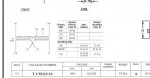
In my 2013 GE catalog, they list two transformer models in your voltage use case 120/240 - 600V. One with taps, like your Acme drawing, and one without taps. You need to check yours to be sure what you have. Your transformer sizes appear to be adequate for the load values you gave.


For your transmitter #2, T3 transformer, I would put the disconnect at the transformer location, not 500' away, or both locations if you need that.
MTW Ω


 hmy:
hmy:
