Sub Feed Panel

Status
Not open for further replies.

crossman

Senior Member
Location
Southeast Texas
Re: Sub Feed Panel

Actually there is a difference between the open neutral ahead of the subpanel versus the open neutral ahead of the service panel.

The difference is that the service panel is presumably at the same potential as the earth and sorrounding conductive items because it is tied to all of the "available electrodes" (or is that "present electrodes") and all of the equipment grounds are still at ground potential.

In the subpanel, this is not the case. Very different.
 

crossman

Senior Member
Location
Southeast Texas
Re: Sub Feed Panel

okay, enough of the quiz...

The subpanel enclosure will be HOT, the drill motor frame will be HOT, in fact, ALL of the subpanel equipment grounds will be HOT with respect to earth.

[ January 03, 2005, 06:26 PM: Message edited by: crossman ]
 

iwire

Moderator
Staff member
Location
Massachusetts
Re: Sub Feed Panel

Originally posted by crossman:
The difference is that the service panel is presumably at the same potential as the earth and sorrounding conductive items because it is tied to all of the "available electrodes" (or is that "present electrodes") and all of the equipment grounds are still at ground potential.
We like to think so, but the only way that is true is if the house is fed with a metal water service that is also bonded at the neighbors.

Without that metal water pipe the other electrodes (rods, plates, concrete encased) will do very little to limit the voltage rise of the enclosures in relation to earth.

An open service neutral to a house with a plastic water main is just as dangerous as your sub panel example.

I do agree with you that is another good reason for 4 wire feeds and it is also why I like that ranges and dryers newly installed must have a 4 wire branch circuit. :)
 

crossman

Senior Member
Location
Southeast Texas
Re: Sub Feed Panel

Absolutely agree on the part about dryers and other appliances that were allowed to be "grounded" with the neutral. I can't believe they ever let that one be done.

Now, back to the other discussion. You grab the drill from the subpanel. I'll grab the drill at the service panel. We'll see who hollers the loudest! :)

Down here where I am from, we have that dark clay soil which is almost always wet. It conducts pretty darned well. I feel certain that even a single ground rod is going to do well in limiting the shock potential to a person in this scenario. Certainly the loads are going to be acting quite funny.

Perhaps in other locales, your assessment of the grounding electrode situation may certainly be correct.

And if your assessment is correct, then isn't this a huge hazard which should be addressed by the NFPA? Perhaps we need to do a whole lot more to ensure that electrical equipment is connected to good electrodes?

PS. Thank you for the welcome to the forum, iwire. :) This place is very very interesting!
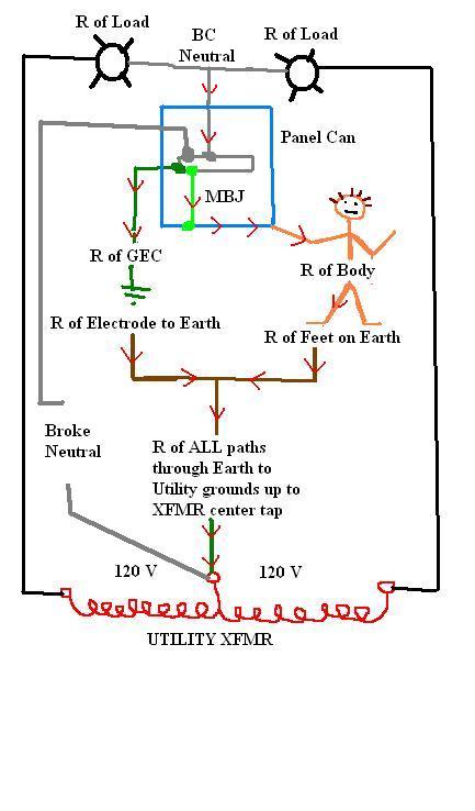
[ January 03, 2005, 07:06 PM: Message edited by: crossman ]
 

iwire

Moderator
Staff member
Location
Massachusetts
Re: Sub Feed Panel

You are certainly correct that the location will have a great influence on the effectiveness.

Picture this the code asks for a ground rod to be 25 ohms or less or you have to add one.

Lets say you manage to get 20 ohms.

120 volt fault into a 20 ohm ground rod equals only 6 amps of current flow on the GEC.

As electricity takes all available paths if you walk up and touch the meter socket you are very likely to become one of the paths.

The grounding electrodes are only used to limit the voltage imposed by lightning, line surges, or unintentional contact with higher-voltage lines and to stabilize the voltage to earth during normal operation.

That is pretty much what 250.4(A)(1) tells us, notice "stabilize the voltage to earth during normal operation

In my opinion that is the NEC telling us that the grounding electrodes will not stabilize the voltage to earth during abnormal operation.
 

crossman

Senior Member
Location
Southeast Texas
Re: Sub Feed Panel

>>>>I have been reading the forums here and at the ECN website and I am learning tons already. I am certainly glad I found these websites. I have my opinions on most subjects, but if I throw out something that is wrong, you folks please please jump in and correct me! Thanks!<<<<

I thought about this subpanel open neutral versus service panel open neutral a bunch. I came up with the following drawing of circuit paths for the service panel with an open neutral. It is somewhat more complicated than just saying that we have 120 volts across a 20 ohm grounding electrode as far as I can tell.

This panel of course has a MBJ to the can and a GEC to an electrode. Again, the neutral from the utility is open. A guy is touching the panel enclosure (equipment ground) and standing on the earth (barefoot).

*Excuse the crayon mess... nothing but MSPaint at home. :)

1) Do y'all think this is representative of the paths that exist? If not, where did I go wrong?

2) If I am correct, plug in some reasonable ohm values for each part of the circuit, then do the Ohm's Law calcs and see how much voltage the fortunate man is subjected too.

*Darn it I keep finding mistakes! Assume that the two black hot wires to the loads are going through the panel and circuit breakers before they hit the loads.

GROUND_PATH.JPG


[ January 04, 2005, 12:00 AM: Message edited by: crossman ]
 

crossman

Senior Member
Location
Southeast Texas
Re: Sub Feed Panel

Here is the same drawing for subpanel with an open neutral in the feed. Remember, there is no GEC or electrode and the neutral bus is bonded to the can and the equipment grounds. Again, add in reasonable ohm values and do the Ohm's Law calcs on this one to see what voltage is impressed across our unfortunate homeowner.

GROUND_PATH_sub.JPG
 

iwire

Moderator
Staff member
Location
Massachusetts
Re: Sub Feed Panel

Crossarm I like your drawings. :)

Originally posted by crossman:
If I am correct, plug in some reasonable ohm values for each part of the circuit, then do the Ohm's Law calcs and see how much voltage the fortunate man is subjected too.
In this case it could be 120 volts.

He is in parallel with the other electrodes.

The question is how much current will flow through him?

Likely enough to kill.
 
Re: Sub Feed Panel

Am i totally missing something? If you disconnect the ground from the neutral at the original panel if the neutral isn`t bonded to the cabinet how does the equipment grounding conductor trip the breaker in fault. if it has to rely solely on the rod for return path. It`s like having no ground at a metal pole and driving a rod the breaker won`t trip if thats the sole path for fault current.At the original panel you have only 3 wires so doesn`t the grounded and grounding connect?
 

crossman

Senior Member
Location
Southeast Texas
Re: Sub Feed Panel

iwire:

Thank you for complimenting my drawings. I sort of like them too! :)

I am hoping to develop a better understanding of how this all works. Do you agree that my two drawings are essentially correct as far as the paths current will take in the two differing circumstances?

Does anyone else have anything to say about these two situations? I see the service panel situation as being very much safer than the subpanel situation.

I am thinking that we are on the verge of making some profound discoveries about grounding here. We need to put some indepth thought into this so I (we?) can get a grasp of what is going on here and why the code rules are what they are.

Look at the things that are in series before and after the parallel parts. Is it possible to impress 120 volts on the person in the Service Panel drawing?

[ January 04, 2005, 09:14 AM: Message edited by: crossman ]
 

crossman

Senior Member
Location
Southeast Texas
Re: Sub Feed Panel

Originally posted by reel-break:
Am i totally missing something? If you disconnect the ground from the neutral at the original panel if the neutral isn`t bonded to the cabinet how does the equipment grounding conductor trip the breaker in fault.
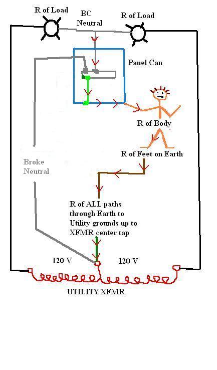
This situation actually has nothing to do with tripping breakers under fault current. There is no fault at the moment. What I am saying is that using the "grounded" conductor as an equipment grounding conductor on the load side of the service has the potential to make the panel cans and any other equipment grounds and the frames of equipment HOT. No breakers trip because there are no faults.

I guess that is why the situation is so dangerous.
 

crossman

Senior Member
Location
Southeast Texas
Re: Sub Feed Panel

Concerning the service panel with open neutral:

* I hope someone actually reads this and gives it some thought. Perhaps more myths will be dispelled? If anyone sees any problems in my thinking here, please correct me, because I am really trying hard to understand and grasp the theory of these code rules.

The way I see it, the person is in parallel with only the GEC and the electrode point of contact with the earth. And that parallel path is in series with the loads and with the resistance of the earth back to the utility xfmr. Because voltage drops divide up in series, the human will not be in contact with anywhere even close to 120 volts. Most of the voltage drop is going to occur in the earth path back to the xfmr.

The only way the guy could receive a significant shock is if the resistance of the GEC and connections was very high or if the contact resistance of the electrode to earth is very high (and these according to Soares have neglible resistance) or if it is near infinite like in the subpanel with no electrode.

Let?s look at Soares Book on Grounding to see what they say about the resistance of electrodes:

Pages 108 and 109 paraphrased:

The GEC and connections, and the electrode themselves have very little resistance : ?the overall resistance is negligible?

The National Institute of Standards and Technology has demonstrated that the resistance between the electrode and the surrounding earth is negligible if the electrode is free of paint and grease and if the earth is firmly packed.

The only component remaining is the resistance of the earth itself and this resistance will be spread through the earth along the path of conduction.


So an assumption of ?20 ohm grounding electrode? is not the electrode itself, it is the resistance of the dirt path that is being measured! And this resistance of the dirt path is also in SERIES with the human.

Let?s calculate from my drawing:

First Case

Assume only one phase wire is supplying current, all the loads on the other phase are turned off. (for simplicity of calculations)

Assume

4 ohm load resistance (120 volt, 30 amp load under normal conditions)
GEC resistance = 0 ohms
Electrode contact with earth = 1 ohm
Resistance of earth path back to xfmr = 50 ohms (pretty lousy ground really)
Resistance of body = 150,000 ohms
Resistance of feet to earth = 10 ohms
Person is using the same 50 ohm path back to xfmr

Ohm?s Law of series-parallel circuit yields less than 3 volts on the human.

Second Case

Same as above except now there are 4 ohms of connected load on one phase and 20 ohms of connected load on the other phase.

Calculating by superposition, the human gets shocked by less than 2 volts.

Much different than the case of the subpanel where the guy is receiving the full 120 volts (maybe 119 volts)
 

don_resqcapt19

Moderator
Staff member
Location
Illinois
Occupation
retired electrician
Re: Sub Feed Panel

crossman,
I see 111 volts on the human in case 1. You have a 50 ohm resistance in parallel with a 150,050 ohm resistance. This gives an effective resistance of 49.98 ohm for the two in parallel. The 49.98 is in series with the 4 ohm load. Using ohms law solve for the circuit current. 120/53.49 = 2.22 amps. Now solve for the voltage drop across the load. 2.22(4) = 8.88 volts dropped accosts the load. That leaves 111 volts to fry the human.
Don
 

crossman

Senior Member
Location
Southeast Texas
Re: Sub Feed Panel

The way I am looking, the human is not in parallel with the 50 ohms. That 50 ohms exists in the dirt all the way back to the utility xfmr ground. He is in series with that 50 ohms, not in parallel with it.

I have been wrong before. If I am wrong here, please show me. :)

Is my drawing wrong? Isn't the person in series with the long dirt path of 50 ohms back to the xfmr?

[ January 04, 2005, 11:45 AM: Message edited by: crossman ]
 

crossman

Senior Member
Location
Southeast Texas
Re: Sub Feed Panel

I think a point of confusion here is that when a grounding electrode is tested and you come up with 50 ohms, it isn't the electrode that has the 50 ohms, it is the dirt path that is actually being tested.

This pretty much comes from Soares Book on Grounding pages 108 and 109

The guy is in series with that 50 ohm dirt path.
 

wirenut1980

Senior Member
Location
Plainfield, IN
Re: Sub Feed Panel

Crossman, I like the drawings! I see the GEC resistance and the person's resistance being in parallel and those two resistances in series with the 4 ohm load. That being the case, I agree with Don, 111 V on the person. Good discussion. :)
 

crossman

Senior Member
Location
Southeast Texas
Re: Sub Feed Panel

Okay, you guys have me thinking. I read the article and am not convinced yet.

The first thing that comes to my mind is this...

The person's bare feet standing on the ground ALSO have a 30 inch sphere of resistance and it is actually a lot higher resistance than the electrode 30" of resistance. These two 30" spheres are in parallel for the most part I think.

I presume that the 30" sphere off the feet has more resistance than the 30" sphere around the electrode because of contact area and depth.

I still see the guy in series with 50 ohms.

Question: The current that flows through the person's body... where is it going?
 
Status
Not open for further replies.
Top