mstrlucky74
Senior Member
- Location
- NJ
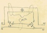
in video he shows three different ways that the three ways can be wired you guys mostly wire it one way or varies often.
https://youtu.be/_u5ORnhqn8g
Sent from my SM-N960U using Tapatalk
https://youtu.be/_u5ORnhqn8g
Sent from my SM-N960U using Tapatalk