Timer Current Curve pickup

Status
Not open for further replies.

mbrooke

Batteries Included
Location
United States
Occupation
Technician
At what point does this time current curve start timing? It appears somewhere between 1 and 2x, but I am having trouble obtaining an exact value.
 

Attachments

  • time overcurrent curve.jpg
    time overcurrent curve.jpg
    130.7 KB · Views: 0

Smart $

Esteemed Member
Location
Ohio
The timing starts at the zero (0) second reference. It is not shown. The chart is a 'window' plot, i.e. zero is not depicted one or both axes. For example, you could have an even smaller plot window by hiding the part below .09 seconds and to the left of 1.5x pickup and still have the same data plot.
 

mbrooke

Batteries Included
Location
United States
Occupation
Technician
The timing starts at the zero (0) second reference. It is not shown. The chart is a 'window' plot, i.e. zero is not depicted one or both axes. For example, you could have an even smaller plot window by hiding the part below .09 seconds and to the left of 1.5x pickup and still have the same data plot.

Still confused. It must have a pickup point, before that there is no timing.
 

Sahib

Senior Member
Location
India
Still confused. It must have a pickup point, before that there is no timing.
Each curve in the picture touches multiple of current 1. So the timer can start at full load current value if so set. So what is not clear?
 

mbrooke

Batteries Included
Location
United States
Occupation
Technician
Each curve in the picture touches multiple of current 1. So the timer can start at full load current value if so set. So what is not clear?

The black lines rest against (start) in between 1 and 2, not 1 hence the confusion.
 

mivey

Senior Member
At what point does this time current curve start timing? It appears somewhere between 1 and 2x, but I am having trouble obtaining an exact value.
IIRC it will start at about 1.1 or 1.2 X. I have a note in my stack of stuff if I can put my hands on it. Will look later today.
 

mbrooke

Batteries Included
Location
United States
Occupation
Technician
IIRC it will start at about 1.1 or 1.2 X. I have a note in my stack of stuff if I can put my hands on it. Will look later today.

Thats what I was looking for, I would certainly be interested :) I'd like to have exact control over the pickup threshold.
 

mivey

Senior Member
Thats what I was looking for, I would certainly be interested :) I'd like to have exact control over the pickup threshold.
For EM relays, you test the pickup to be within 3% of 1X. However, the EM relays are not very accurate below 1.5X so that is why you make sure your minimum desired operating point is at least 1.5X (like for minimum ground faults at end of line, etc.).

A relay may pick up at 1X but it may take 5 minutes to operate so you have to decide if that is good or not.

Suppose maximum current is 75 amps for a high impedance fault and you want to catch it. Suppose at a 74A pu it takes 24 minutes to operate: is that ok? If you add a 10% safety factor, now you might pick up in 3 minutes. But allowing a 150% factor on a 75A pu (use a 50A pu) means you might pick up in 30 seconds which is more acceptable.

Digital relays are spot on but you still need to add at least a 10% safety factor for misc accuracy.
 

mivey

Senior Member
By digital relays being spot on I don't mean exact to the nth decimal place but the difference is negligible in every application I work with.

Once you have some reasonable zone separation that accounts for other variances like breaker operating times, signal latency, etc. the digital relay inaccuracy is not really a factor.
 

iceworm

Curmudgeon still using printed IEEE Color Books
Location
North of the 65 parallel
Occupation
EE (Field - as little design as possible)
S$ -
I have not heard of the term "window plot". The paper is "Log-Log" - logarithmic on both axis. Doesn't matter what "window" one picks, neither axis will ever get to zero. But I'm thinking you already knew that.

(slow poster - edit to add) Adding to Mivey's response:

... I'd like to have exact control over the pickup threshold.
mb -
Most TCC come with a lot of notes that define the curves and tolerances. If the notes don't come with the TCC, the mfg will have them buried somewhere. I guess they could say, "It meets UL xxx." But I have never seen that.

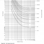
The TCC you attached is likely a Thermal Magnetic, i^2t . When you find the notes, the likely wide tolerances isn't any where close to "exact". If one sketches the tolerances on the TCC, the trip curves are really thick. The usual interpretation is, at any given current, the CB may trip at the shorter time, and will trip at the longer time.

Consider the UL489 spec is: never trip at 100%, must trip in one hour at 135 % (condensed, paraphrased - not exact wording) Most trip units are better than this - but one has to look at the notes for the tolerances.
(edit to add) You didn't say what you have for a trip unit, however, since the TCC shows an i^2t with a time dial, it likely not an ordinary molded case. The UL489 example is just that - an example of acceptable tolerances.

The top of your TCC is only 10 seconds. To stretch it out to an hour (3600 seconds is three more decades - double the height of the chart. Without the notes, the chart is telling us that above 10 seconds the curve gets really, really, really long.

Possibly you would be interested in an electronic LSI trip unit. Often those are easier to fit over a motor starting curve or a xfm energization curve. And, of course, more money = tighter tolerances.

According to my first instructor in a coordination class. With enough money, you can coordinate anything."

Hope this helped - although I suspect you likely already knew this.

ice
 
Last edited:

mivey

Senior Member
I forgot to note: A digital relay, such as SEL will start at >1X. It is formula based and will not time until current is greater than pickup (exactly 1 would give a divide by zero formula error).

For very small fractions above 1X, the time will be extremely long or may not even trigger the timer logic due to A/D resolution limits.
 

mbrooke

Batteries Included
Location
United States
Occupation
Technician
I forgot to note: A digital relay, such as SEL will start at >1X. It is formula based and will not time until current is greater than pickup (exactly 1 would give a divide by zero formula error).

For very small fractions above 1X, the time will be extremely long or may not even trigger the timer logic due to A/D resolution limits.

Is this for all microprocessor relays or just SEL?


You are indeed correct, it is equation based. Does this mean I follow the equations in the manual and ignore the time current curves? And if so, then why have these time current curves in the first place? Unless they are just generics?
 

mivey

Senior Member
Is this for all microprocessor relays or just SEL?
I was thinking some were 1.1-1.2X but I only had time to look at SEL today. Will try to look more later.
You are indeed correct, it is equation based. Does this mean I follow the equations in the manual and ignore the time current curves? And if so, then why have these time current curves in the first place? Unless they are just generics?
The curves are matching historic and universal curves. Follow the equations and logic diagrams for digital relays. With the modifiers we usually add, the published curves are usually just for reference anyway.

Equations are one thing but how the combination of CTs, relays, and breakers along with their associated variations actually respond under different fault conditions is another.
 

mbrooke

Batteries Included
Location
United States
Occupation
Technician
I was thinking some were 1.1-1.2X but I only had time to look at SEL today. Will try to look more later.
The curves are matching historic and universal curves. Follow the equations and logic diagrams for digital relays. With the modifiers we usually add, the published curves are usually just for reference anyway.

Equations are one thing but how the combination of CTs, relays, and breakers along with their associated variations actually respond under different fault conditions is another.


Fair enough. I can live with the response variables, but would like to know the exact pickup values.
 

Sahib

Senior Member
Location
India
I think you need have actual fault conditions to know exact pick up values. Have you got those data to work out exact pick up values?

Or do you want to use it for overload protection, which may not be feasible?
 
Status
Not open for further replies.
Top