Trough size and conductor bending radius

Status
Not open for further replies.

tiger4life

Member
Location
Alabama
Occupation
Business Manager Electrical Construction/Master Electrician
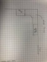
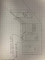
We are installing a 800 Amp SER ATS between the POCO Transformer and existing MDP, we were going to intercept those feeds in a trough around to new ATS then back to MDP.
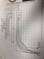
The trough will be mounted under MDP to intercept 2 - 4" PVC C with 4 - 500 MCM each which we will use inline Polaris or compression lugs to extend to ATS, inspector says there is not enough room to bring conductors into trough because we will not comply with bending radius which my understanding is there is nothing in NEC to deal with bending radius on anything less than 600 volt and this is 277/480 Volt system.
The trough will start under panel and carry on around the wall to the ATS location then another trough above the other one back to MDP. I have 18" from floor to bottom of MDP to fit a trough, MDP is 12" deep. We were planning to use a 16" x 16" trough which has 51.2 usable SQ IN.
 
You must comply with 314.28, and I believe 312.6 for far wall. So that doesn't specifically address 500 KCMIL bend radius, but it does spell out the minimum size, and from what you describe you comply. Perhaps send a sketch.
 
You must comply with 314.28, and I believe 312.6 for far wall. So that doesn't specifically address 500 KCMIL bend radius, but it does spell out the minimum size, and from what you describe you comply. Perhaps send a sketch.
Here is a rough sketch I see you are from Ocala FL, I have family that lives down there mainly my father. He lives off 200 right before you get to "Top of the World"
 

Attachments

  • Photo Feb 03, 11 40 29 AM.jpg
    Photo Feb 03, 11 40 29 AM.jpg
    70.8 KB · Views: 31
  • Photo Feb 03, 11 40 38 AM.jpg
    Photo Feb 03, 11 40 38 AM.jpg
    82.4 KB · Views: 31
I don't think it really applies but if it did I would consider this an angle pull, but we are entering the bottom of the wireway then going to the left around the wall and into the side of the ATS and instead of chase nipples we could use a wireway transition into ATS.
 

Attachments

  • Photo Feb 03, 12 03 56 PM.jpg
    Photo Feb 03, 12 03 56 PM.jpg
    134.3 KB · Views: 16
You could probably get away with using two LBL’s into tap can, then extend from there with two 4” to the service rated transferswitch, then back with two more 4” to the existing mdp.
 
Here is a rough sketch I see you are from Ocala FL, I have family that lives down there mainly my father. He lives off 200 right before you get to "Top of the World"
I live about 25 minutes from there over near Silver Springs, but I drive over there to golf sometimes.
 
He is retired from Golden Flake, he was head of Maintenance there.
 
IMO, 376.12(A) would apply requiring a bending radius per 312.6)A) and your wireway would be adequate. From your OP, it appears the conducto0rfs to the ATS would be service conductors and as such would have to be separated from the load side conductors per 230.7
 
IMO, 376.12(A) would apply requiring a bending radius per 312.6)A) and your wireway would be adequate. From your OP, it appears the conducto0rfs to the ATS would be service conductors and as such would have to be separated from the load side conductors per 230.7
  • That is correct Sir on the Service conductors and load will come back to MDP in separate wire way.
  • Since this is not considered an angle pull 314.28(A)(2) is not in play here or 376.23(b) from my understanding.
  • A wire-way is considered an extension of a enclosure, the only part of 312.6 (a) is where conductors enter ATS to terminate.
  • NEC does not regulate bending radius for conductors under 1000 volts except for what is in 312.6 (a) pertaining to terminals and width of gutter.
  • 376.20 Being in parallel I will need to group separate each parallel feed
  • Wireway Size
    • 8- 500 kcmil THHN x 0.7073 = 5.6584 sq in
    • Total equals = 5.6584 sq in
    • Since 20% is equal to one-fifth
    • 5.6584 sq in x 5 = 28.292 sq in
    • Largest wire-way we can use for this location 16" x 16" = 256 sq in so we are good here (I'm not concerned with finding smallest size but always look for largest size possible within reason)
    • 256 sq in x 20% = 51.2 sq in
    • 256 sq in x 75% = 192 sq in if taps are made
I believe after discussing with you guys (Thanks) and after investigating myself I am on the right track and comply with NEC.
Am I missing or misunderstanding anything?

NOTE: I also talked to a local head inspector here and I ran through the above and what I was wanting to do and he agreed I was well within code. He did mention that on wire bending radius you should comply with conductor manufacture specs witch is usually 7 to 8 times the diameter of conductor.
 
Never mind, the LL’s are not rated for 500’s, they make a 4” mogul that is, but. It in a LL configuration.
Yea I mentioned the LL's to one of my guys and he said the same. So you can get a 4" Mogul in a LL?
 
Didn’t see one listed, only in LB form. The manufacturer I checked was Appleton, maybe another manufacturer has it.
Yea because of space the Wireway is the way we will go and feel good about it.
 
Status
Not open for further replies.
Top