- Location
- Placerville, CA, USA
- Occupation
- Retired PV System Designer
Smart $...
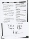
I strongly contend your assertion that all three windings of the delta-connected generator contribute to the load current is invalid. My simple proof... convert the delta-connected generator into a wye-connected one.
Now if you truly understand Electrical Theory, you must be aware of a very basic tenet, i.e., it is possible to substitute a wye-arrangement for a delta-one, and vice-versa!
Thus, if you substitute a wye-generator for the delta-one, and connect the load to say terminals A and B, terminal C has no connection to the load!
Phil
I think you are misusing that basic tenet. It is absolutely correct that you can substitute a delta for a wye and vice versa without having any effect on what is on the other side of the three terminal points. It certainly can make a difference as to what is going on inside the delta or wye device.
Here is one example: If you have a simple series circuit, coming out of a black box with terminals A and B, you can measure anything you want at those terminals and not be able to tell the difference between a current source with a parallel resistor and a voltage source with a series resistor. But from the point of view of th heat generated within the box, you there will certainly be a difference.
The windings in wye are not the same coils of wire that are used to make a delta of the same voltage, and the way that the current/power comes from the three windings will be different. But from the point of view of the load, there will be no difference.