pct2607
Member
- Location
- Huntsville Alabama
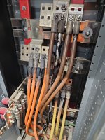
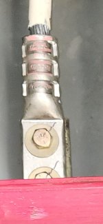
We were called out to a customer's site today and found that all four sets of the feeder conductors of a 1200A service have been overheating and melting away the insulation. It appears that it was torqued because of the sharpie mark on the bolt and when my guys took it apart the nuts were tight. First glance tells me that it maybe that each crimp does not appear to have been compressed correctly, but again I'm not 100% sure. We are in the process of getting this repaired and will monitor the load for several days. Has anyone seen this before?
Thanks,
Peter
Thanks,
Peter