
andrewc23
Member
- Location
- Philadelphia, PA
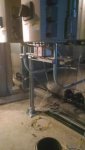
I am a mechanical contractor with limited electrical expertise. We have (4) large 30,000 CFM air handling units. They have 6 supply fans and 4 return fans in an array. The supply fans are broken up and fed by two separate VFD's. Same for the return fans.
During start-up the drive tech was able to get each of the drives to operate individually. However, when he put the 2nd drive for each array, both drives went totally wonky. They wouldn't operate and it appeared to cycle from lots of different modes.
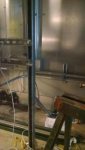
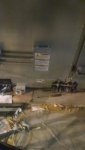
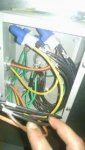
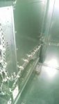
The 480V drives feed separately in conduit do a factory supplied junction box on the outside of the unit. From there, the electrician connected to factory run wiring to each fan array. These (6) wires are bundled together from the junction box to just before they split and go to each array. There is a thought that these cables being bundled is backfeeding noise into the drives.
One other note - there are control wires on each drive and also harmonic filters prior to the drives.
Any advice or insight would be greatly appreciated.
During start-up the drive tech was able to get each of the drives to operate individually. However, when he put the 2nd drive for each array, both drives went totally wonky. They wouldn't operate and it appeared to cycle from lots of different modes.
The 480V drives feed separately in conduit do a factory supplied junction box on the outside of the unit. From there, the electrician connected to factory run wiring to each fan array. These (6) wires are bundled together from the junction box to just before they split and go to each array. There is a thought that these cables being bundled is backfeeding noise into the drives.
One other note - there are control wires on each drive and also harmonic filters prior to the drives.
Any advice or insight would be greatly appreciated.
")