- Location
- Placerville, CA, USA
- Occupation
- Retired PV System Designer
Read The "Factory" Manual.
(Generally, the "F" stands for something other than Factory though...)
Yes, it stands for "Fine", right? :angel:
Read The "Factory" Manual.
(Generally, the "F" stands for something other than Factory though...)
Read The "Factory" Manual.
(Generally, the "F" stands for something other than Factory though...)
Read The "Factory" Manual.
(Generally, the "F" stands for something other than Factory though...)
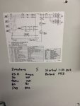
My guess was drive was already smoked and that had a lot to do with why fuse was blown. By replacing fuse and energizing he just got to see why the fuse was blown the first time.This piece of equipment, including the drive was installed and an electrical contractor made the electrical connections years ago, awhile back we experienced some power issues to this building; lost phase. When the power came back up AHU-1 did not start, shop HVAC tech found blown 90a fuse, fuse was replaced, power was turned on and POW, drive smoked. The tech was concerned about the wire size (3-#6's and a #12G) on 50 amp breaker. I have been tasked with correcting the obvious problems with wire size and breaker size. The electrical drawings show 1 20hp motor when there are 2, it also shows 3-#8's and #10G. I have been working with the in house electrical engineer to try and figure out how this happened and who is responsible. I have been reading the "Factory" manual and see that there may be other issues with this install, the wire from the motors to the drive are separate #8 thhn with #10G tie-wrapped together and secured to the inside of the motor enclosure. The engineer stands by his recommendation of 3-#4's and #6G on 110a breaker. The "Factory" manual states: AC Mains Connection- Size wiring based upon the input current of the frequency converter. I will admit I do not have much experience with drives, what I know now is from reading information from the TRANE website on the TR200.
My guess was drive was already smoked and that had a lot to do with why fuse was blown. By replacing fuse and energizing he just got to see why the fuse was blown the first time.
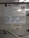
Still working on this, still confused, according to the "Trane Drive operating Instructions", 2.4.4 AC Mains connections: Size wiring based upon the input current of the frequency converter. For maximum wire sizes see 10.1 Power-dependent specifications. Going to page 69 table 10.6 Mains Supply 3X380-480 V AC, in the P37K column, Max. Input current, Continuous(3X440-480V) [A] is 59 Intermittent(3X440-480V) [A] is 64.9
KISS it! (keep it stupidly simple) The code requires you to size the supply conductors to the VFD based on the VFD rating x 1.25 (430.122). If you have a 59A VFD, that's just what you need to install for. That intermittent rating is just an overload capacity of the drive which is 10% of its continuous rating.
Another acronym, not the way I heard it said but I like your definition better. VFD input current= 170.2A X 1.25 =212.75 seems awful high for something driving 2-20hp motors, been doing a lot of reading on this subject seems I'm not the only one confused. As I said previously, this was install and wired years ago and until recently it worked fine as wired; although the equipment ground was the wrong size for a 50a breaker.
430.122 essential trumps the other rules because things are different with a VFD. You can use a VFD at its rated output current, but because everything is programmable, that may or may not relate directly to the actual motor size. For example I can install a 50HP rated VFD and use it on a 25HP motor. If I sized the conductors for the 25HP motor, the input current for the VFD might become higher than that some day in the future if someone changes the motor to 30, 40, or 50 HP because they see that the VFD is rated for that. The input conductors would be too small then. So the NEC addressed this by requiring, in 430.122, that those conductors FEEDING the VFD must be sized based on the VFD maximum input amp rating. But remember, this is only pertaining to the MINIMUM size of the CONDUCTORS, not the circuit protection.Here is something I found that seems to contradict what some people have said:Sizing conductors for VFDs
... Here is an example: from a 70-ampere (A) breaker in the MCC, 8 AWG wire was run to a disconnecting means where we have now installed a VFD. The motor at full load does not draw more than 37.8A at 480 volts (V). We are being told that we are in violation of Section 430.122 and that all wiring from the MCC to the VFD needs to be replaced. What is the correct answer?
...
430.122 essential trumps the other rules because things are different with a VFD. You can use a VFD at its rated output current, but because everything is programmable, that may or may not relate directly to the actual motor size. For example I can install a 50HP rated VFD and use it on a 25HP motor. If I sized the conductors for the 25HP motor, the input current for the VFD might become higher than that some day in the future if someone changes the motor to 30, 40, or 50 HP because they see that the VFD is rated for that. The input conductors would be too small then. So the NEC addressed this by requiring, in 430.122, that those conductors FEEDING the VFD must be sized based on the VFD maximum input amp rating. But remember, this is only pertaining to the MINIMUM size of the CONDUCTORS, not the circuit protection.
Down stream of the VFD, the drive is protecting the motor, and the drive is controlling the amps, including starting current. Think of the VFD as a completely new power source for the motor, with its own protection scheme. The feeder breaker size then need only be based on what the DRIVE needs on the input side, not the motor. I've heard (but not yet seen) that the next code revision is going to address the OCPD sizing for the DRIVE, but at this point it is not there yet. That's why you just stick to what the drive is listed with, which should be in their manual (assuming it is UL listed, because UL requires it).
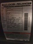
40HP worth of 460V motors does NOT need a VFD rated for 172A, something is wrong there. The VFD would only need to be rated at around 52-60A at most. It says on the nameplate that the motors themselves are rated 27A each, so that's 54A total if there are two.VFD input current= 170.2A X 1.25 =212.75 so why are the fuses at 1F40,1F41,1F42 JJS-100