Wiring between step up and step down transformers

Status
Not open for further replies.

Strathead

Senior Member
Location
Ocala, Florida, USA
Occupation
Electrician/Estimator/Project Manager/Superintendent
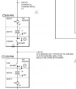
We have an engineered system. The project is a new be tower for a hospital, so the need is supplying the emergency system from the generation plant (CEP). It steps the voltage up from 480 to 4160 and back down to 480/277 a few hundred feet away. There are some inconsistencies. Note that both transformers and all interconnection wiring is outside.

The drawings show, a Wye/Wye step up and a Delta/Wye step down. See the attached drawing. Square D supplied a step up transformer that they describe as 4160GY/2400 primary 480 Delta secondary (which is obviously reversed in terms), and a step down of 4160 delta to 480Y/277 secondary. Not what the drawings show.

All that said, regardless of what is on the one line, what is required for wiring?

First, feeding the primary of the step up. Did it need a neutral as shown if the primary was Wye and why?

Next does the secondary require the common point (neutral) to be grounded to a grounding electrode system as shown?

Does the interconnection require the ground to be pulled between them and if so, what is the code section? Also please explain why it is or isn't required.

Any speculation on why the engineer drew is one way, and Square D submitted it another way, which the engineer didn't reject.
 

Attachments

  • One line.jpg
    One line.jpg
    56.1 KB · Views: 43
First, feeding the primary of the step up. Did it need a neutral as shown if the primary was Wye and why?

A wye:wye transformer requires a neutral on the primary side. This is because the primary L-N current mirrors the secondary L-N currents, so if you don't have a primary neutral the secondary appears to be an open neutral. The exception to this is if there is an alternate path that permits secondary L-N currents to be matched. For example the transformer could have a 'tertiary' delta coil set (a set of three phase coils connected in delta that don't have any external connection); circulating current in the delta coils could provide for L-N current on the secondary without a primary neutral.

So perhaps the the delta:wye transformer was substituted to avoid the need for the neutral.

I don't have the experience with MV systems to answer on the grounding requirements.

-Jon
 
Most customer owned systems do not use eyelets transformers for stepping up from 480V, this is likely why Square D submitted con a standard design product.

For grounding you would normally treat a step-up transformer similar to your typical step-down configuration.
 
I think what they provide for transformers is good. For your step up you want 480 Delta to 4160gy/2400. Sounds like this would be a multi-grounded neutral MV system (259.184(C)). Step down is the wye-wye. But.... That doesn't seem to correspond with what is shown on the drawing and the medium voltage conductors shown. I would use 15kv 1/3 concentric neutral with "my idea". I think you need to get some clarification.


But yes you need a EGC between the two, which could be the neutral conductor if it's a multi-grounded neutral system, review 250.184.
 
Most customer owned systems do not use eyelets transformers for stepping up from 480V, this is likely why Square D submitted con a standard design product.

For grounding you would normally treat a step-up transformer similar to your typical step-down configuration.
what is an eyelet transformer?
 
I think what they provide for transformers is good. For your step up you want 480 Delta to 4160gy/2400. Sounds like this would be a multi-grounded neutral MV system (259.184(C)). Step down is the wye-wye. But.... That doesn't seem to correspond with what is shown on the drawing and the medium voltage conductors shown. I would use 15kv 1/3 concentric neutral with "my idea". I think you need to get some clarification.


But yes you need a EGC between the two, which could be the neutral conductor if it's a multi-grounded neutral system, review 250.184.
You are the only one who answered the installation portion of this at all. Google searches have also been useless. I am a little surprised others haven't helped to clarify, but...

So, first off, the Wye secondary on the step up transformer seems superfluous. I don't see any requirement to install a neutral between the two transformers. Because of that, it looks like I can install a single-point grounded system with a #6 ground to two ground rods and a 1/0 (oversized to match the plans) copper bonding jumper between the grounding and the grounded in the supply transformer, then run a #1/0 ground as shown and no neutral which would be basically what is depicted in the one line I included.

Otherwise, it would be a multi-point that would consist of #6 grounding electrode conductor to two #6 ground rods at each transformer, a supply side bonding jumper connecting the ground bus and the neutral at each transformer.

what am I missing?
 
With the disclaimer that I am not an experienced MV guy, but have done a few small MV systems:

I don't see much of a reason to NOT go with an MGN system. For single phase runs it's a no brainer as u would only need one cable. But even for three phase, The way I see it, CN cables are the least expensive type of MV cable, and you will need some sort of bonding conductor between the transformer anyway, so why not just go with 1/3 neutral concentric cables which take care of your bonding?
 
Also, I assume you probably have no control over the engineering side of this, but something seems way off. So they are using 500 aluminum to run 4160 just a couple hundred feet? I get like .2% voltage drop at 2 MVA! I would run it at 7200 with 15KV AL CN URD, I mean why not? I don't see any advantage staying with 5 KV class.
 
Also, I assume you probably have no control over the engineering side of this, but something seems way off. So they are using 500 aluminum to run 4160 just a couple hundred feet? I get like .2% voltage drop at 2 MVA! I would run it at 7200 with 15KV AL CN URD, I mean why not? I don't see any advantage staying with 5 KV class.
I understand what you are saying, but these transformers are already set, no one had looked too closely to our final install before this. So it is what it is. But since there isn't a neutral connection point on the load side, are you saying we would just connect the neutral straight to the grounding point on that side? That doesn't seem to be kosher.
 
I understand what you are saying, but these transformers are already set, no one had looked too closely to our final install before this. So it is what it is. But since there isn't a neutral connection point on the load side, are you saying we would just connect the neutral straight to the grounding point on that side? That doesn't seem to be kosher.
So which transformer is the step up?
 
I think the "GY" designation means the wye point is factory bonded to the tank. I think you just run your MV EGC and bond it to the tank along with the 480 supply EGC. Then at the other end it also bonds to the transformer tank along with a GES for that Lv side. Basic yeah per your post #6. I'll have to read thru 250.184 to be sure🤔. If you drift off of MGN systems I get confused 😉
 
I understand what you are saying, but these transformers are already set, no one had looked too closely to our final install before this. So it is what it is. But since there isn't a neutral connection point on the load side, are you saying we would just connect the neutral straight to the grounding point on that side? That doesn't seem to be kosher.

Every time you 'derive' a new system, you need to ground it afresh (assuming you want a grounded system, which is most common). If a neutral is available, it is the neutral that gets grounded, even if the neutral isn't used for a circuit conductor.

Jon
 
Every time you 'derive' a new system, you need to ground it afresh (assuming you want a grounded system, which is most common). If a neutral is available, it is the neutral that gets grounded, even if the neutral isn't used for a circuit conductor.

Jon
However If this is a wye-wye, and assuming the secondary wye point is factory bonded, then it wouldn't be an SDS
 
Every time you 'derive' a new system, you need to ground it afresh (assuming you want a grounded system, which is most common). If a neutral is available, it is the neutral that gets grounded, even if the neutral isn't used for a circuit conductor.

Jon
Respectfully, that doesn't clarify anything.
 
I'm not sure that I understand your question. So I'm going to start at the beginning, most likely stating things that you already know. This is not meant as disrespect, but rather to provide a basis to understand where we are misunderstanding each other.

As I understand things:
Grounding is electrically connecting your electrical power system to all of the 'ambient' (in the surrounding area; proximal is probably a more accurate term, but ambient conveys the feeling better) conductive materials.

The purposes of grounding are
1) Provide a fault current path in the event that one of your electrical power conductors comes in contact something conductive nearby. If your electrical power system is ungrounded, then you could have a fault to surrounding materials that does nothing but create a high voltage hazard.
2) Limit transient voltages imposed by external sources. There are many high voltage, low current/charge sources of energy around; these can damage insulation even though their available energy is miniscule. You don't want random static zaps creating arc damage through your 600V insulation.
3) Limit elevated voltages caused by re-striking faults. These are voltages created when the natural parasitic capacitance of a system interacts with the natural parasitic inductance of a system in the presence of an intermittent ground fault. This creates a situation where the L-L voltage of a system pumps the L-G voltage of the system. L-G voltages can exceed L-L voltages.

Grounding is performed by connecting a single terminal of your electrical supply to conductive materials which are then bonded to non-current carrying metal, and connected to an earth electrode.

When a _single_ terminal of your electrical supply is connected to 'ground', then you don't have a closed circuit, and current doesn't flow into the 'ground' connection. This is why you must have only, but only one connection between your electrical system and ground.

So if you are supposed to ground at one, but only one location, why isn't there just a single massive ground connection that handles the entire electrical grid? Because the grid is _not_ a continuous 'system'.

In this case, 'system' means the set of wires with a direct galvanic connection, meaning that (given enough time), current could flow from one point on a system to another. In particular, transformers break the galvanic path. _Power_ flows between the primary and secondary of a transformer, but current does not. In a transformer, current on the primary interacts with the magnetic flux in the core, which interacts with current in the secondary. You could imagine a transformer as an electric motor, coupled via an insulated shaft, to an electric generator. The secondary terminals 'derive' a new electrical system which needs to be grounded.

You might choose for design reasons to create an ungrounded system, but this generally requires the use of ground fault detection hardware and supervision to repair ground faults when they are detected. Or you might choose to 'corner ground' or 'resistance ground' a system. But common (and usually best) practice is to ground the neutral of each new system, even when that neutral is not used as a circuit conductor.

In the system described in the OP, you have a grounded wye 480/277V system supplying a 4160/2400V:480V wye:delta transformer used as a step up. There is no place to land a neutral on the 460V 'primary'. The neutral of the 4160/2400V wye secondary is not used by a circuit conductor. However the conductors here have no galvanic connection to the grounded supply and the 4160V is 'derived' from the changing magnetic flux of the transformer. So _if_ the 4160/2400V system is to be grounded, the neutral of this transformer is the place to do it.

Does any of the above help clarify things, or at least help refine the question? Or did I miss some key piece of the original question?

-Jon
 
Jon,

I would say his questions are clearly stated in the OP:
First, feeding the primary of the step up. Did it need a neutral as shown if the primary was Wye and why?

Next does the secondary require the common point (neutral) to be grounded to a grounding electrode system as shown?

Does the interconnection require the ground to be pulled between them and if so, what is the code section? Also please explain why it is or isn't required

My answers are:
1. I am not sure on this
2. I don't see any requirement to ground this MV system, but it may depend on the design of the transformer, that is the wye point may be factory bonded and not removable and if so that decision is made. My first though is might as well ground/bond the wye point as that typically lowers the insulation levels of conductors for MV, and I can't think of a disadvantage.
3. Definitely need a "ground" pulled between the two transformers, however note the neutral could serve this purpose for MGN MV systems (and also that exception for LV outdoor SDS's).

What are your thoughts on these points Jon?
 
1) In general, a wye:wye transformer requires a neutral brought to the primary, because otherwise the wye:wye derives a high impedance neutral. However in the case of the OP, the previous wye:wye transformer was only feeding L-L loads. In this case I am not sure if you _need_ to bring a neutral to the wye primary. This is moot because the transformer actually supplied was a delta:wye

2) My understanding is that having ungrounded MV systems is more common and more generally permitted than having ungrounded <600V systems. If the designer _chooses_ to ground the MV system, then grounding the wye point is the correct way to do this. I think this might be the confusion of the OP, the _reason_ for " just connect the neutral straight to the grounding point on that side"

3) I agree. Could reasonably be a combined grounded conductor/egc. But there must be some fault current path.

-Jon
I think post #11 strat said the step up is the wye-wye
 
Status
Not open for further replies.
Top