"Dirty" voltage on bus.

Status
Not open for further replies.

moonshineJ

Member
Location
USA
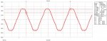
Yes. The distortions you see is a result of non-linear load, a rectifier bridge to be more specific. These are 5th and 7th harmonics.

To get really technical, I always hated calling semiconductor devices (like diodes and transistors) "non-linear" loads. A reactor can also be non-linear (swing choke) having variable inductance based on current.

They should call semiconductor devices "non-differentiable response devices" because during their change of state (open/close) derivative of output signal does not exist.

Discontinuity? What physical value would be derivative of signal on output?
 

GoldDigger

Moderator
Staff member
Location
Placerville, CA, USA
Occupation
Retired PV System Designer
Discontinuity? What physical value would be derivative of signal on output?
The physical value would be the "rate of change of current", which is not something that has a short name or a familiar interpretation.

If the current instantaneously changes from zero to non-zero, the rate of change is infinite.
In the real world that does not happen. But you can approximate the actual waveforms in modeling software by assuming that the current waveform is in fact not differentiable, and in fact not even continuous.
But with any kind of reactive components (but particularly inductive), a discontinuous current can correspond to in infinite applied voltage.
 

Besoeker

Senior Member
Location
UK
I know but I imagine that much harmonics result in significant voltage distortion as well (depending on source impedance). Also, IEEE 519 has guidelines for current as well as voltage.
Yes, I know about IEEE 519. We ship equipment to countries where we have to comply.
 

Jraef

Moderator, OTD
Staff member
Location
San Francisco Bay Area, CA, USA
Occupation
Electrical Engineer
... They should call semiconductor devices "non-differentiable response devices" because during their change of state (open/close) derivative of output signal does not exist.
I like the term, I've had to explain what "non-linear" means when teaching a class that was not really about that specific detail, I had just used the term when discussing harmonics, then some smart alec will want to know what that means. I have a canned answer that satisfies the masses for the most part, but I get lost in the weeds on that one if I get a real persistent person who wants to have me explain my explanation.

But one suggestion: if we call it Non-differentiable Electrical Response Devices, we can use the acronym NERD...

That way I can say things like "Harmonics are the result of NERDs used in the electronic power conversion devices present in almost all aspects of our modern life.""
 

LMAO

Senior Member
Location
Texas
I like the term, I've had to explain what "non-linear" means when teaching a class that was not really about that specific detail, I had just used the term when discussing harmonics, then some smart alec will want to know what that means. I have a canned answer that satisfies the masses for the most part, but I get lost in the weeds on that one if I get a real persistent person who wants to have me explain my explanation.

But one suggestion: if we call it Non-differentiable Electrical Response Devices, we can use the acronym NERD...

That way I can say things like "Harmonics are the result of NERDs used in the electronic power conversion devices present in almost all aspects of our modern life.""

haha...
 

LMAO

Senior Member
Location
Texas
The physical value would be the "rate of change of current", which is not something that has a short name or a familiar interpretation.

If the current instantaneously changes from zero to non-zero, the rate of change is infinite.
In the real world that does not happen. But you can approximate the actual waveforms in modeling software by assuming that the current waveform is in fact not differentiable, and in fact not even continuous.
But with any kind of reactive components (but particularly inductive), a discontinuous current can correspond to in infinite applied voltage.

You are correct. In real world, there always IS a derivative. Signals never change state instantaneously because Fourier transform of a stop function contains infinite number of frequencies, which is impossible.

I must say I am really impressed by the knowledge of some you guys; most electrical engineers I know are not nearly as knowledgeable as some posters here...
 

GoldDigger

Moderator
Staff member
Location
Placerville, CA, USA
Occupation
Retired PV System Designer
You are correct. In real world, there always IS a derivative. Signals never change state instantaneously because Fourier transform of a stop function contains infinite number of frequencies, which is impossible.

I must say I am really impressed by the knowledge of some you guys; most electrical engineers I know are not nearly as knowledgeable as some posters here...
In a former life stage I was a physicist (high energy particle flavor). :)
 

moonshineJ

Member
Location
USA
The physical value would be the "rate of change of current", which is not something that has a short name or a familiar interpretation.

If the current instantaneously changes from zero to non-zero, the rate of change is infinite.
In the real world that does not happen. But you can approximate the actual waveforms in modeling software by assuming that the current waveform is in fact not differentiable, and in fact not even continuous.
But with any kind of reactive components (but particularly inductive), a discontinuous current can correspond to in infinite applied voltage.

Delta aye over delta tee. Fair enough; thank you.
 

moonshineJ

Member
Location
USA
Alright, here is how
"extremely dirty with really bad clipping on peaks"
wave shapes look like. I guess the guy didn't have the O-scope with 600 V capacity. He checked voltage not on 450 VAC, or phase to ground, but on regular lighting circuit after x-former.
 

Attachments

  • 1.jpg
    1.jpg
    79.7 KB · Views: 0

LMAO

Senior Member
Location
Texas
Alright, here is how
"extremely dirty with really bad clipping on peaks"
wave shapes look like. I guess the guy didn't have the O-scope with 600 V capacity. He checked voltage not on 450 VAC, or phase to ground, but on regular lighting circuit after x-former.

Looks like harmonics caused by NERDs. Just like Golddigger said, if you have a current clamp get a shot of current waveform. The distortion will be a lot more visible.
 

moonshineJ

Member
Location
USA
Looks like harmonics caused by NERDs. Just like Golddigger said, if you have a current clamp get a shot of current waveform. The distortion will be a lot more visible.

Unfortunately, they don't have that type of stuff. Also, if one gets a shot of voltage at different points of bus, (even at 115 side downstream off 450/115 VAC stepdown x-formers), the shapes would be identical.

While if one gets a shot of current at different locations of power distribution tree, the shapes of current would look very different, say at:
- output bus of 3 phase 450 VAC generator
- output wire form VFD to 3 phase motor
- 240 VAC washer/dryer
- 115 VAC fluorescent lamps branch ?
 

LMAO

Senior Member
Location
Texas
Unfortunately, they don't have that type of stuff. Also, if one gets a shot of voltage at different points of bus, (even at 115 side downstream off 450/115 VAC stepdown x-formers), the shapes would be identical.

While if one gets a shot of current at different locations of power distribution tree, the shapes of current would look very different, say at:
- output bus of 3 phase 450 VAC generator
- output wire form VFD to 3 phase motor
- 240 VAC washer/dryer
- 115 VAC fluorescent lamps branch ?

I honestly don't think you necessarily need to see the current. This is obviously harmonics due to non-linear devices. My question is: what are they asking for? clean up power line? They need some sort of active or passive filtering, or place a reactor upstream to their drives....
 

moonshineJ

Member
Location
USA
I honestly don't think you necessarily need to see the current. This is obviously harmonics due to non-linear devices. My question is: what are they asking for? clean up power line? They need some sort of active or passive filtering, or place a reactor upstream to their drives....

Well, this is a good point. When I saw this wave shape today, I told them that there is not much to worry about. I thought they have something like a cardiogram on their distribution bus. Nope. I guess there is some disagreement with electronics folks, saying that voltage may have to do something with their stuff.... I'll let them to sort it out....
 

kwired

Electron manager
Location
NE Nebraska
Alright, here is how
"extremely dirty with really bad clipping on peaks"
wave shapes look like. I guess the guy didn't have the O-scope with 600 V capacity. He checked voltage not on 450 VAC, or phase to ground, but on regular lighting circuit after x-former.
But that voltage source is from on site generation as mentioned in your OP, correct? Throw the second generator on line or supply from utility and the waveform is cleaner - correct? Sure your POCO distribution transformers still have impedance but the prime mover of their generation supply is much larger and isn't as effected by your loads as the prime mover on your local generator is.

Still comes down to a larger source is more stout then the smaller source and will overcome those peaks getting clipped easier then a smaller source will, but the current wave will still be similar in either instance.
 

moonshineJ

Member
Location
USA
But that voltage source is from on site generation as mentioned in your OP, correct? Throw the second generator on line or supply from utility and the waveform is cleaner - correct? Sure your POCO distribution transformers still have impedance but the prime mover of their generation supply is much larger and isn't as effected by your loads as the prime mover on your local generator is.

Still comes down to a larger source is more stout then the smaller source and will overcome those peaks getting clipped easier then a smaller source will, but the current wave will still be similar in either instance.

That's right. Clean power while coonnected to utility, a bit dirty power from one generator, and more dirty from another one. When both gens are in parallel, it's seems power is ok. I suggested them to take snapshots of power from each gen's ouput, with the load breakers open, so nothing would affect this test. It's important, because different people take readings using different equipment, under different conditions, at different points. Looking at this screen it's hard to tell if there is any problem. I would rather use the old good CRT scope, not this one.
 

Attachments

  • 2.jpg
    2.jpg
    105.1 KB · Views: 0

Besoeker

Senior Member
Location
UK
That's right. Clean power while coonnected to utility, a bit dirty power from one generator, and more dirty from another one. When both gens are in parallel, it's seems power is ok. I suggested them to take snapshots of power from each gen's ouput, with the load breakers open, so nothing would affect this test. It's important, because different people take readings using different equipment, under different conditions, at different points. Looking at this screen it's hard to tell if there is any problem. I would rather use the old good CRT scope, not this one.

I use a digital scope with a backlit LED display.
It gives excellent results and I can dump the data into a spreadsheet for later analysis.

HomeVrev01_zpsecc9f579.jpg
 
Status
Not open for further replies.
Top