You can"t do that!
You can"t do that!
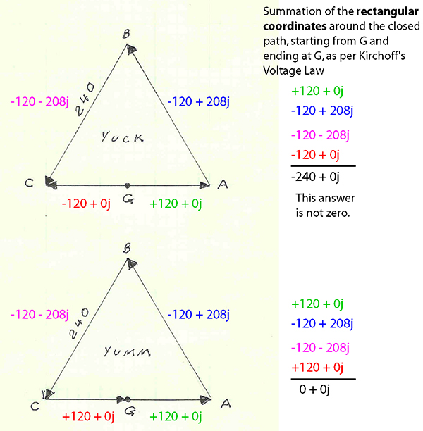
Can't do that Rick. You have changed the reference on Vcg so it adds instead of subtracts. This is absolutely wrong! Both 120V phasors must be drawn tail to tail! In other words, you screwed up my perfectly good diagram.
You can"t do that!
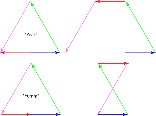
Rick Christopherson said:The thing about phasors and vectors, is that no matter what order you place them, the answer is still the same. It doesn't matter if you walk 20 feet north, 20 feet west and 20 feet east, versus walking 20 feet west, 20 feet north, and 20 feet east--you still end up at the same place. This shouldn't be news to anyone that has spent any time with phasors or vectors.
So to put this into perspective, I have redrawn "Yuck" and "Yumm", only I changed their order. As you can see, when you place "Yuck" tip-to-tail in standard phasor/vector addition, the result is suddenly a 240 volt gap. When "Yumm" is rearranged, it looks like an hourglass, but still closes back to the original point.
To reiterate what I said in the previous thread, I don't care whether or not someone wants to call the two halves of the transformer out of phase or not. That is a matter of semantics that I do not need or want to argue. My issue was on the use of "phasors" as a justification for making the argument.
New Edit I apologize for this, and I do try to avoid editing a posting that has been posted for over an hour now, but since it is so late at night, I don't think this edit should screw anyone up. The reason for my edit was because I scrolled back up to the top of this thread and read the original posting, as follows:I added the Bold emphasis. This is directly applicable to the diagram I drew above, and is why I edited this posting to restate the original topic. The diagram I drew represents proper phasor/vector summation.
Can't do that Rick. You have changed the reference on Vcg so it adds instead of subtracts. This is absolutely wrong! Both 120V phasors must be drawn tail to tail! In other words, you screwed up my perfectly good diagram.