You are using an out of date browser. It may not display this or other websites correctly.
You should upgrade or use an alternative browser.
You should upgrade or use an alternative browser.
Four-wire delta, phasors, and Kirchoff:
- Thread starter rattus
- Start date
- Status
- Not open for further replies.
Come on someone:
Come on someone:
Let's have somone sum the voltages around this loop which includes head to tail and head to head.
Rick? Winnie? Mivey? Carl? Anyone?
Come on someone:
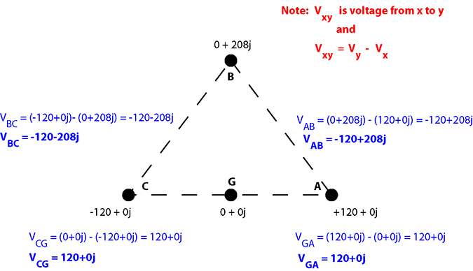
rattus said:Please open the attachment which is a partial phasor diagram of a 120/208 wye. (Post #78)
Now, we already know that Van = 120 @ 0 and Vbn = 120 @ -120. How would one use KVL and phasors to determine the magnitude and phase of Vab?
Let's have somone sum the voltages around this loop which includes head to tail and head to head.
Rick? Winnie? Mivey? Carl? Anyone?
Last edited:
- Location
- Massachusetts
Rick Christopherson said:I hate to say this
So why did you?
but your understanding of the principles you are arguing is so light that you don't even realize that you have just grossly contradicted your founding premise.
And that helps the civil discussion how?
Come on folks, this has been great, we have a bunch of new blood in here with new thoughts and ideas and while the majority of the discussions have been beyond me it is great to have new topics here at the forum.
 Please don't drag them down with the this petty bickering.
crossman
Senior Member
- Location
- Southeast Texas
mivey said:If it is a terminology difference, just use the other person's terminology (even if you don't like it) and see if you have the same understanding of the concept.
Excellent advice. And the difference in terminology and given assumptions has definitely detracted from our discussions over the past couple of weeks.
Rick Christopherson
Senior Member
You are correct, and I apologize. It has been very difficult to read the contumelious tone of Rattus' postings (even crossing threads to throw barbs) and not let it get to me at times. What I said, I did not say in anger. I had walked away from the computer for 2 hours before making that posting. What I said was an observation, not an intentional insult.iwire said:So why did you?
Nevertheless, as inappropriate as that opening was, it does not change the magnitude of the statement made (Re: CW Vs CCW), and I would like to hear a response.
Last edited:
- Location
- Wisconsin
- Occupation
- PE (Retired) - Power Systems
All this talk about KVL, lets not forget that current also needs to be evaluated.
Given: a system defined as two voltages connected in series with a single 2 wire resistor connected to the resultant V12. Isn't there a single load current and two source currents? And shouldn't the source currents be in the same direction as their voltage?
The way I see this discussion:
In Rattus' system, with sources V1n and V2n the source current from one of them has to be opposite its voltage.
In Rick's system, with sources V1n and Vn2 the source currents are in the same direction as their voltages.
I know that both systems can be solved (after all if, A' = -A then -A' = A). But, one of them is more intuitive to me as an engineer that the other.
Either way:
Either way:
CW or CCW, but not both. I worked the problem with a CCW path; My summation equaled zero. Should be nuf sed.
Now respond to my post #78 which contains head to head phasors. How do we treat them?
Either way:
Rick Christopherson said:Nevertheless, as inappropriate as that opening was, it does not change the magnitude of the statement made (Re: CW Vs CCW), and I would like to hear a response.
CW or CCW, but not both. I worked the problem with a CCW path; My summation equaled zero. Should be nuf sed.
Now respond to my post #78 which contains head to head phasors. How do we treat them?
jim dungar said:All this talk about KVL, lets not forget that current also needs to be evaluated.
Given: a system defined as two voltages connected in series with a single 2 wire resistor connected to the resultant V12. Isn't there a single load current and two source currents? And shouldn't the source currents be in the same direction as their voltage?
The way I see this discussion:
In Rattus' system, with sources V1n and V2n the source current from one of them has to be opposite its voltage.
In Rick's system, with sources V1n and Vn2 the source currents are in the same direction as their voltages.
I know that both systems can be solved (after all if, A' = -A then -A' = A). But, one of them is more intuitive to me as an engineer that the other.
Just trying to demonstrate that V1n and V2n exhibit a phase difference of 180 degrees, and I have done that. The current will take care of itself. If you and Carl prefer the yumm diagram, that is perfectly OK. Winnie prefers the yuck diagram when working with the 120/240 subsystem. To each his own though.
Cause I like to have math models be consistent as they move from the simple to the complex.mivey said:How about one diagram for the three-phase phasors and one diagram for the single-phase phasors? ...
follow this trail of bread curmbs:wink:
So you like this one:
carl
Rick Christopherson
Senior Member
I find this dismissive and insulting. If this forum is going to hold me to a standard of decorum, then it should be holding you to the same standard, and so far that does not appear to be equivalent.rattus said:Should be nuf sed.
========================================
When you did your voltage summation around the closed path, you went:
CCW from G to A...A to B...B to C.....and then changed and went CW from G to C. The reason for presenting a nodal diagram was to show this, and you have already agreed that the previously shown nodal diagram was accurate. Now that you have agreed this diagram was accurate, I have filled in the voltages between the nodes, making sure to move in a counterclockwise direction.
The CCW voltage between C and G is (0+0j) - (-120 + 0j) = (120 + 0j). Conversely, your voltage between C and G, which was measured CW (clockwise) was (-120 + 0j).
So without realizing it, you changed from counterclockwise to clockwise in your summation when you got to nodes C and G. This is the reason why you needed to subtract.
Diagram Notes: The voltage from point X to point Y is defined as the voltage of Point Y minus the voltage of point X.
Also Note that I prefer my voltage naming convention to be Vab = voltage from a to b. I mention this only because I have noticed my convention is opposite from Rattus', but it does not play a role in this discussion so long as we know this and do not intermix the two.
====================================
====================================
No, I will not respond until we are through with this topic. I have only been here a few weeks, but I have already learned that one of your primary tactics in a discussion is to distract others away from a difficult problem by redirecting them to another issue. We'll come back to it after you have addressed the current issue.rattus said:Now respond to my post #78 which contains head to head phasors. How do we treat them?
- Location
- Wisconsin
- Occupation
- PE (Retired) - Power Systems
rattus said:Just trying to demonstrate that V1n and V2n exhibit a phase difference of 180 degrees, and I have done that. The current will take care of itself.
Why do you dismiss this little issue? In a purely resistive circuit your system has one source whose voltage is "180? out of phase" with its current. So are these equations the correct ones for your system, V1n=IR and V2n=-IR?
[B said:mivey][/B]
How about one diagram for the three-phase phasors and one diagram for the single-phase phasors? ...
If one extends the poor model, it gets real funny looking. And as jim pointed out in posts, 86 and 94, the currents don't follow the sources real well.coulter said:Cause I like to have math models be consistent as they move from the simple to the complex. ...
I really would like an answer. Do you like "poor" well enough that you are willing to end up at "puke"? Cause that is the logical extension of "poor".
carl
jim dungar said:Why do you dismiss this little issue? In a purely resistive circuit your system has one source whose voltage is "180? out of phase" with its current. So are these equations the correct ones for your system, V1n=IR and V2n=-IR?
Jim, let the current be I12 which is in phase with V1n. Then the sense of the current is leaving V1n and returning to V2n. You would expect the return current to be out of phase with V2n--not unlike return current in a DC circuit.
Now, if we sum all phasors except the one in question, the sum comes out to be 120 @ 180 (relative to ground) Now add in the last phasor, either yucky, or yummy. The sum is still 120 @ 180.
- Location
- Wisconsin
- Occupation
- PE (Retired) - Power Systems
rattus said:Jim, let the current be I12 which is in phase with V1n. Then the sense of the current is leaving V1n and returning to V2n. You would expect the return current to be out of phase with V2n--not unlike return current in a DC circuit.
If the current is I12 and it is in phase with one source V1n then it must also be in phase with the other source.
I expect resistive current to be in phase with its source voltage. Yours can not be, especially if the source is a center tapped transformer referenced as you have.
Rick Christopherson said:I hate to say this because the discussion has been going moderately well, but your understanding of the principles you are arguing is so light that you don't even realize that you have just grossly contradicted your founding premise.
You just asserted that the "Summation is clearly stated as CCW", yet you defined your voltage between points C and G in a clockwise fashion.
This is the single most critical point I have been making from the very outset. You have defined all of the voltages in your phasor diagram in a counterclockwise direction, with the exception of the voltage between points C and G. You defined this voltage in the clockwise direction.
Here is a hint: Take a look at the nodal analysis diagram that you have already agreed was correct.
I will address the rest of your posting at a later time, but I do not want to distract you from this single, rather critical, point.
Rick,
This is the way it works.
The path of the summation is a closed loop either CW or CCW. It has nothing to do with the direction of the phasor arrows.
Phasors, being complex numbers, can easily be added or subtracted.
If the phasor arrow points in the same direction as the path, we add.
If the phasor arrow points in the opposite direction, we subtract.
That is all there is to it. If you still disagree, give us a reference that proves me wrong.
Rick Christopherson said:So without realizing it, you changed from counterclockwise to clockwise in your summation when you got to nodes C and G. This is the reason why you needed to subtract.
Diagram Notes: The voltage from point X to point Y is defined as the voltage of Point Y minus the voltage of point X.
Also Note that I prefer my voltage naming convention to be Vab = voltage from a to b. I mention this only because I have noticed my convention is opposite from Rattus', but it does not play a role in this discussion so long as we know this and do not intermix the two.
====================================
====================================
No, I will not respond until we are through with this topic. I have only been here a few weeks, but I have already learned that one of your primary tactics in a discussion is to distract others away from a difficult problem by redirecting them to another issue. We'll come back to it after you have addressed the current issue.
Looks valid to me. Now draw in the phasor arrows, and you will see that you have reversed the arrow between C & G making that a voltage rise, that is,
+120 + j0.
But, that is no different from -(-120 + j0) which also yields a correct result.
Yes, subtraction is allowed.
Furthermore, the point -120 + j0 is the same as 120 @ 180 degrees.
Now, I am pressing you on the partial wye problem because that phasor diagram contains head to head phasors, and solving for Vab should end this discussion.
jim dungar said:If the current is I12 and it is in phase with one source V1n then it must also be in phase with the other source.
I expect resistive current to be in phase with its source voltage. Yours can not be, especially if the source is a center tapped transformer referenced as you have.
Jim,
But Jim, it can be, e.g.,
I12 = (V1n - V2n)/R = 240/R @ 0
Now V2n = 120 @ 180 which is out of phase with I12.
Compute I21 and its phase angle is 180 degrees.
This is what makes phasors so tricky.
Consider a 208V resistive load in a wye. The load current is not in phase with either source.
- Status
- Not open for further replies.